

What is Shearing and Bending in Ships?
All kinds of floating vessels are subjected to a wide range of forces and moments. In a broad sense, external loads acting on the vessel from the water medium are of two kinds: i) external and ii) internal.
External loads, in turn, can be defined into several kinds: predominantly the buoyancy loads, manifested as hydrostatic pressure force vectors acting directly on the hull structure, and the other sources of forces stemming from hydrodynamics, vessel motions and interactions, wind forces or weather loads, and some miscellaneous time-varying loads like on-board operational loads and other effects. The internal loading is from the vessel itself, essentially the weight distribution of a vessel.
The total weight of the vessel acting on the water is supported by the balancing buoyancy forces or an upward reaction thrust in order to maintain a state of physical equilibrium such that the vessel remains afloat, as we know from the simple Archimedes’ principle.
In a global sense, when we talk about the hull girder as a whole, the problem can be simply visualised as a singular body in a state of equilibrium where the aggregate weight of the vessel acting through the centre of gravity or CG is supported or balanced by the counteracting equal and opposite buoyancy force (acting through the centre of buoyancy) and the vessel, as a result, remains afloat.
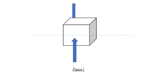
For a symmetric body in perfectly still water conditions, the centre of buoyancy and the centre of gravity are colinear. This is nothing but the simplest case of the floating box we had first seen while understanding the concept of Archimedes’ principle for the hydrostatic equilibrium of a body. The following simple free-body diagram shows a box-shaped vessel floating in Stillwater conditions.
However, for more practical real-world problems like a seagoing vessel, the concept of flotation reaches a new advanced dimension even though fundamentally the same.
Shearing and Bending
Now, let us recap what a shear force is. Shear force is a tangential component of force that acts in a coplanar manner that is parallel to the plane of the face of the object, as shown. If the object deforms relative to the line of reference, it is known as shear strain.
In solid mechanics, shearing is common to all bodies that are subjected to lateral or tangential forces acting in the opposite sense.
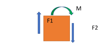
Now, look at the following figure that forms the simplest basis for this concept. The body is subjected to a force couple (F1 and F2) acting on the two faces in a sense opposite to each other. Since there is a counteracting force couple, the body has a tendency to deform relatively with respect to its two faces. Moreover, due to this force couple, there is also a moment as seen, and hence the body tends to bend, or in other words, gets subjected to a bending moment, M.
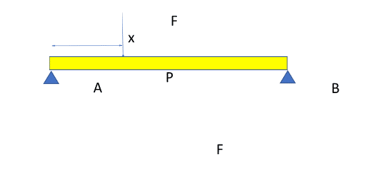
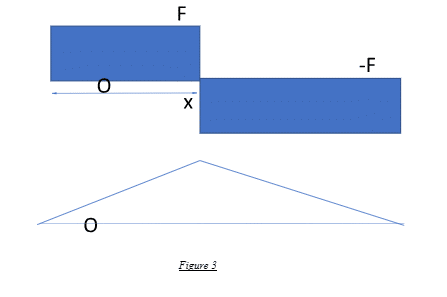
Now, look at the next figure. There is a simple beam that is supported at the two ends. Consider a downward force acting at an arbitrary distance, say x, from one of its ends, say A. What happens? As obvious, the beam tends to bend towards the direction of the applied force.
Hence, consider the free body diagram from the end A to the point where the load is acting (point P) as shown. This force, F, though a normal force in a global sense that acts perpendicular to the beam as a whole is also a shear force that acts tangentially coplanar to the cross-section of the beam at that point P. Due to this applied force, there is a reaction at the support point A, acting in the opposite sense.
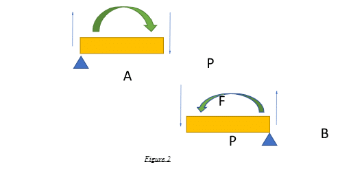
This force couple is essentially shearing on the beam section between points A and P and creates a moment in a clockwise sense, as shown.
Similarly, if we consider the free-body force diagram in the other section of the beam, from P to the other end-support point, say B, the bending moment is in an opposite or counter-clockwise sense.
Hence, the beam, as a whole, is subjected to a net bending moment that causes a flexural tendency in the downward direction due to the effect of the applied load P.
The bending moment is essentially associated with the flexural or bending behaviour of beams due to the application of loads. In mechanical terms, when we deal with the flexural nature of bodies subjected to different degrees of loading, shear stresses acting coplanar to the material cross sections per unit area is the more appropriate term that is used.
Shear forces are, thus, tangential and coplanar forces that act along the face of the body, and when there are two opposite shear forces relative to one another, the body is said to be under a shearing effect. The bending moment results from shear forces acting on a body during shearing that causes the body to bend.
As we always know from first principles, force multiplied by a linear measure (distance) is nothing but moment. Hence, in the above problem, at the point P, the applied force F multiplied by the distance x yields the bending moment experienced by the beam at P.
Hence, as it is a function of distance, at point A, where x = 0, the bending moment is also zero and linearly increases to the attained value of bending moment, F * x, at point A, as shown. The shear force has a constant value of F from A to P and -F from P to B. The shear force and bending moment diagrams are depicted as follows:
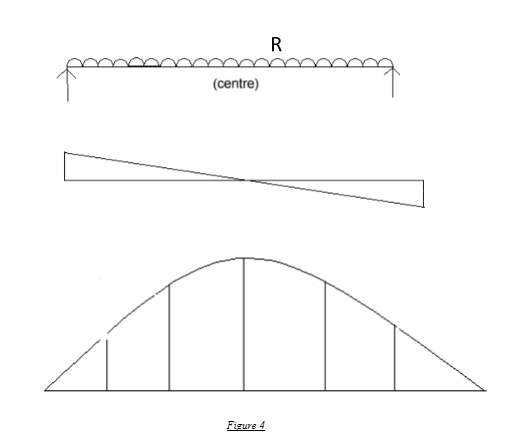
Now consider the same beam under a uniformly distributed loading of, say, R. N/m. The nature of the shear force and bending moment diagrams are given as follows.
In mathematical terms, the integration of shear forces is the bending moment. Conversely, the differential of bending moment yields shear forces. Shear force, in turn, can be considered a summation of all the acting loads over the region of consideration, and the differential of shear force at a given point yields the loading or force distribution at that specific point.
The beam bending or flexural nature of beams subjected to loads under various kinds of conditions is a very important ambit in the realm of statical solid mechanics.
While the simply supported beam with a point load acting is the simplest of all beam problems, there are various kinds of scenarios with myriad combinations of loads (combined, distributed, uniformly varying, random, time-varying, and so on) and support types (fixed, free, partially fixed, cantilever, roller, hanging etc.). All of these are integral to the broad theory of beams in solid mechanics and are not to be discussed here.
Shearing And Bending In Ships
For all practical purposes, a ship can be considered a simply supported beam at any given point in time. Now, let us combine the cases of Archimedes’ simple block floating in water and the simple beam under uniformly distributed loading.
For a floating body, the buoyancy forces are distributed along the entire extent as per the form of the body, the weight distribution, and, of course, the water medium on which it floats.
Like all other forces, the net buoyancy force that acts through the centre of buoyancy, as shown in Figure 1, is essentially the result of the buoyancy forces distribution acting all along the body. This is in response to the weight of the body, which is also distributed along its span and the resultant net acts through the CG.
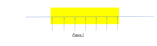
In the idealistic case of a homogenously made simple block problem under perfectly still-water conditions, the weight and the buoyancy forces are uniformly distributed throughout, as shown. Hence, at any given point of the vessel’s hull, there are two counteracting force vectors in opposite directions, the weight or load components acting downward and the buoyancy component acting upwards.
The homogenously-made block has a perfectly uniform weight distribution. And owing to its shape and the perfectly still conditions of the water, the buoyancy distribution imposed also has a perfectly uniform distribution.
Assuming the external conditions are perfectly ideal, the resultant load curve is simply a uniformly distributed loading where, at any given point, the shear force is simply the difference between the weight acting at that point and the buoyancy force at that point.
Hence, essentially, the shear force and bending moment are the same as in the above case of a simply supported beam under a uniformly distributed load.
Now, we know that for a body to float in water, irrespective of anything else, the buoyancy equals the total weight of the body. In the above block problem, for the perfectly ideal case, other than the weight-buoyancy equivalence, at any given point, the weight and buoyancy should also be the same as well. Hence, if the overall weight of the body is W and length, say l, the weight at any given point is W/l.
Henceforth, the buoyancy at the same point should ideally be -W/l, where -W is the net buoyancy force equivalent to the weight. What happens? As expected, the net load at all points in the body is zero! Thus, there is no shearing and bending, with the curves of shear and bending remaining zero, coincident with the reference axes!
However, in the real world, nothing is ideal. Thus, even for a block that you suspend in a tank of water, there is shearing and bending, even though at very low levels, owing to the near-perfect conditions and the uniformity of the body.
In the real world, ships sailing in the sea are very complex cases of flotation. At the end of the day, for any vessel to stay afloat, the net buoyancy equals the total physical weight imposed by the vessel; this value is quantified by a common term, displacement, which is essentially also expressed spatially as the volume of water displaced by the vessel, the action of forces and loads is very much random and complicated.
Now, going back to the beginning of this article, where we had briefly touched upon the load types acting on a vessel, it is important to know that at any given point on the hull, there is an interplay of the following forces:
- The vessel’s weight at that point acts directly on the water
- Buoyancy loads act on the hull with both the Stillwater and the wave component, mostly as outer hull pressure force vectors.
- Hydrodynamic loads in any sea state
- Random loads occur due to vessel motions and dynamics, the interaction of waves with the structure, and related effects.
- Wind forces and other kinds of miscellaneous loads
- Any other time-varying physical effects the vessel may be subjected to.
For all practical purposes, other than the Stillwater buoyancy component, all the above effects are highly time-varying. Even the self-weight distribution of a sailing vessel is somewhat variable owing to reasons like on-board consumption, fuel expenditure, any form of on-board operations (if any), and randomised effects like crew movements or some kinds of live loads.
However, for all practical purposes, for strength assessment of common vessels like cargo, we mostly assume the vessel’s self-weight distribution to be fixed for two major cases: departure or full-load condition, also known as the deep seagoing case, and the arrival or light-load condition, also referred to as the light seagoing case.
For most other vessels where deadweight tonnages are assumed to be mostly fixed every time, the weight distribution pattern can be kept constant.
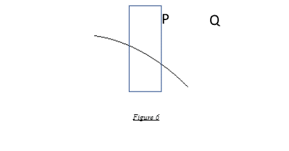
The weight of the ship structure and the buoyancy loads are most important. While the Stillwater component remains fixed for a given draft, the wave component is highly dynamic. Look at the figure below depicting a longitudinal section of a hull. As evident from the wave profile, point P is subjected to higher buoyancy forces than point Q.
Hence, while the aggregate buoyancy of the full ship is equivalent to the displacement for equilibrium, the buoyancy load vector values at any two random points on the vessel can be drastically different from one another.
If you capture a moment in time and isolate the system for studying the loads, in technical terms, it is essentially behaving as a simply supported beam but under the combined influence of very complicated force actions as described above.
These loads can act in any random way and can be of any magnitude at a given point in time. Hence, for the system under consideration, the net load at any given point in the hull can be attributed to the solution of all the described forces at different instances of time. Depending on the local intensities of all the above factors, this aggregate value can also be positive or negative.
Now consider the following situations:
- For example, at a certain location in the hull, where there is a high wave crest which offers a high buoyancy vector upwards, and the weight at that specific point is lesser than this buoyancy force, the effect of all the other force factors above being insignificant relatively, the resultant loading would mostly likely be positive, acting upwards.
- Now consider a random point in the aft where, due to machinery weights, super-structure loads, and high above-hull outfitting loads like boat davits, etc., there is a very high load greater than the buoyancy force vector there. Hence, the resultant force is downwards, with a negative sign!
- Now consider a trickier situation. The sea is mostly calm, and hence, waves are not very random. Now, a vessel passes above a large underwater ridge. Remember squatting? Read about squatting here. For any randomly chosen point on the hull, whenever it passes above the ridge, there is an instantaneous increase in the draft that causes a net downward force (negative) at that very point. Likewise, all the points on the hull experience this effect the moment they cross the tip of this ridge.
- Similarly, for another location on the hull, say somewhere close to the bow region, the weight coming from the vessel almost equals the buoyancy force. However, there is bow slamming there where the bow is periodically impacting the water surface. What happens? At the point in time when the vessel is making contact with the water surface, the net load is acting downwards with a negative value, and when it is rising up, the resultant load is then acting upwards with a positive sense!
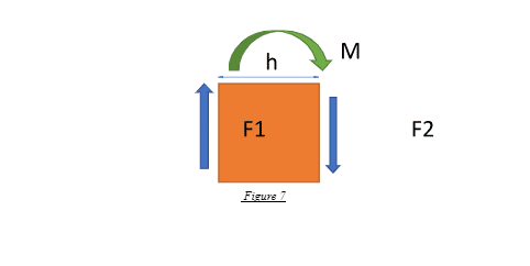
In dealing with studying loads on ships, a frame or a station is a convenient way of defining a particular location on the hull. However, this theory can be applicable to any arbitrarily chosen random point in the vessel’s hull. Suppose we choose station A for convenience and observe a certain random value of loading, say F1 acting upwards, obtained from the culmination of all the above existing effects.
Now, we chose another station B at a certain distance, say h, from A, and there is a net load there, say F2, acting downwards. Due to the dissimilarity, the block between A and B, over the span h, is essentially said to be under shearing! And as we know, shearing leads to a bending moment.
Hence, at any instant in time, integrating all the load points over the length of the hull gives rise to the shearing behaviour of the vessel, essentially known as the shear force diagram in technical terms. Similarly, integrating the shearing forces over the extent of the vessel gives rise to the bending behaviour of the vessel, technically alluded to as the bending moment diagram.
Shearing and bending are integral to the longitudinal strength assessment of all vessels. As the flexural nature of any beam is directly a function of its span or length, in longer vessels, shearing and resultant bending are bigger problems than in smaller vessels.
Having an estimate about the exact shearing and bending nature of a seagoing vessel at all instants of time is beyond the scope of mankind. However, we follow the strength design philosophy such that the vessels are designed and constructed to attain maximum strength against worst-case loading, like always. As bending moment is a direct outcome of shearing, all seagoing vessels are designed and constructed so as to conform to the maximum bending moments feasible as they are expected to experience in their service life.
For all practical purposes, a maximum bending moment is estimated considering the situation where one proper wavelength is equal to the vessel’s length. Though this may be impractical considering the randomness of the sea surface, this is the worst-case scenario that gives us a clear picture of the highest levels of bending moments the vessel can experience.
Like everything in the regime of design and engineering, no value is 100% accurate or exact, and this maximum bending moment taken under consideration is just an estimate but fair enough to give an idea about the loads and moments the vessel can absorb during worst-case conditions.
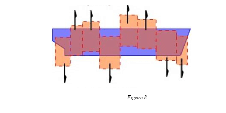
When we consider the wavelength or length of 1 wave to be equal to the vessel’s length, two cases arise:
- The crest or the peak of the wave lies somewhere near the midship, and the troughs or the lowest points lie close to the ends, as shown.
- Two successive crests near the ends, and the trough lies near the middle, as shown.
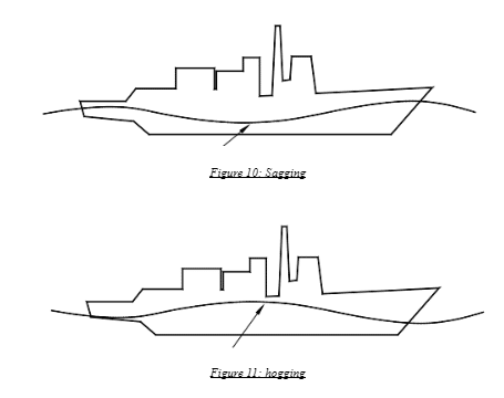
In the former case, the middle body experiences a large and significant component of positive buoyancy force and the ends, due to low wave pressure from the troughs, experience a low or negative buoyancy effect in aggregate terms. Thus, from the nature of such forces, the hull girder behaves as if it is going up near the middle and downwards near the ends.
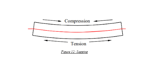
The distinct pattern exhibited by the structure, which causes it to tend to bend upwards near the middle, is known as hogging. The maximum bending moment experienced by the structure is known as the hogging moment. In the hogging case, the main deck is in a state of tension, whereas the bottom shell or fibre is in a state of compression.
In the latter case, due to significant upward forces from the wave crests near the ends, the opposite happens. The hull girder exhibits a curvature going down near the middle, an effect known as sagging, and the maximum bending moment occurring on the structure is the sagging moment. In the sagging case, the main deck is in a state of compression, whereas the bottom shell is in a state of tension.
In longitudinal strength assessment, for all practical purposes, the waves occurring in transverse direction like beam sea or oblique conditions are not considered significant to be contributing to hogging or sagging as they tend to cause deflections of the hull in a lateral sense, as shown.
As a part of basic design, research, and analysis, all vessel structural designs are assessed for longitudinal structural strength to check for shear forces and bending moments for plausible worst-case scenarios.
These are then assessed against allowable rule requirements for maximum values of shear forces and bending moments as per statutory regulations and classification guidelines. If the calculated values are within the given limits, the design is considered safe; else not.
You might also like to read-
- What Do You Mean By Rudder Drop?
- Cold Ironing Ports – Everything You Want To Know
- What is Squatting of Ships?
- What are Tricing Pendants And Bowsing Tackles?
- What Do You Mean By Transit Bearing?
Do you have info to share with us ? Suggest a correction

About Author
Subhodeep is a Naval Architecture and Ocean Engineering graduate. Interested in the intricacies of marine structures and goal-based design aspects, he is dedicated to sharing and propagation of common technical knowledge within this sector, which, at this very moment, requires a turnabout to flourish back to its old glory.


Latest Naval Arch Articles You Would Like:

Subscribe To Our Newsletters
By subscribing, you agree to our Privacy Policy and may receive occasional deal communications; you can unsubscribe anytime.