Understanding Frames in Ships
We are all aware that vessels are composed of complex webwork of stiffening members for resistance to various modes of loading that are oncoming from various sources. The stiffeners are of multiple types, constructions, sizes, and configurations oriented in different ways to meet the requirements of structural strengthening.
Stiffeners can range from longitudinals that run lengthwise across the hull in the deck plating and the bottom shell plating or brackets that connect a plate with an adjoining side stiffener.
In a broad sense, most stiffening members are classified as longitudinal, oriented or aligned along the vessel’s length, or transverse, oriented along the breadth or girth of the ship.
These are for withstanding loads in the longitudinal or lateral directions in a global and local sense. Speaking of longitudinal loads, these are the ones that are involved in the longitudinal effects. Transverse loads are the ones that have their implications on the structure in a lateral direction.

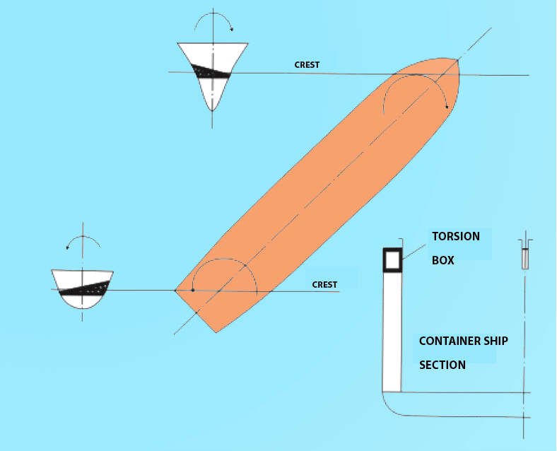
On a global scale, while longitudinal loading mainly includes effects like bending or flexural deflections, transverse loading has effects like racking or torsion. On a local scale, stresses are multidimensional stresses that can act over a particular region or area and still has a fair amount of loading implications on the structure.
For all practical purposes, in a vessel, bottom and deck longitudinals, girders, and stringers (members running longitudinally along the sides) are the primary stiffening members for longitudinal strengthening.
Transverse members include beams, transverse girders, floors, and frames. Frames are the combination of members connected along the girth of a hull and transversely stiffen the outer shell plating as a whole.
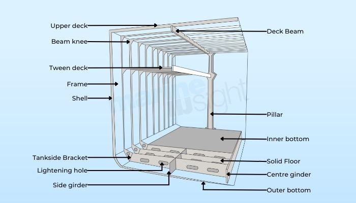
Now, let us discuss this more thoroughly. Suppose there is a standard vessel, and we have a look into one of its transverse sections.
We can see both the transverse and longitudinal members. As we have already mentioned, longitudinal members are the stiffening members that run lengthwise and mainly include the deck and bottom longitudinals, girders (of higher scantlings) or stringers (running along the side shell plating).
We can view the cross-section of these members, including the web and flange.
Transverse Members And Frames In A Ship
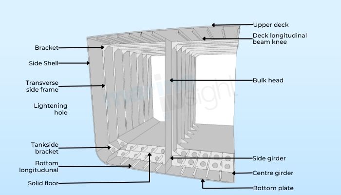
What are the transverse members? These members run laterally all along the hull section’s girth; unlike the longitudinal members, we can see the span of all of these members in our view of interest.
For instance, in a deck, we see that they are transversely stiffened by deck beams that run from side to side. Below the deck are vertical stiffening members connected to the side shell, followed by brackets near the bilge’s turn, which are connected to transverse members that run laterally along the bottom region and stiffen the bottom shell plating.
This entire connection of these members is collectively known as the frame. In layman’s terms, they can be visualised as ribs that comprise our ribcage and encase our heart and lungs.
Likewise, these frames repeated at regular intervals along the entire span of the hull form the ribcage of the vessel and help in transversely strengthening and laterally supporting the hull structure.
Floors And Its Types
The lowermost transverse members are made of vertical plates cut and welded to the bottom shell, plating and running athwartships. These are known as floors.
Floors can be of three types: Solid Floors, Plate Floors and Bracket Floors.
As the name suggests, solid floors are continuous and solid plates with no openings or gaps. These are watertight and oil tight and are used in areas with a heavy incidence of loading, like in machinery or engine room regions, or there is a requirement of water tightness or oil tightness like in tanks.
Plate floors have openings mainly used to reduce unnecessary weight and free passage of fluids like fuel, lubes, or water as required. Bracket floors have large openings and are primarily constructed of brackets fitted at ends. They are used in areas where there is a lesser requirement of strength.
So, floors are essentially the lower components of a frame that extend from the bilge strake to the keel on either side. Besides stiffening the bottommost or outer shell plating, they also serve as foundations for supporting the inner bottom plating (for double bottom constructions) and tank boundaries or machinery foundations.
The type of floor is chosen based on the requirement and the modulus of loading in that particular region of consideration. The depth of the floor is also decided based on the strength requirements.
Side Frames
The upper part of the frames welded to the side shell and run vertically is also known as side frames. For tank construction, the part of the side frame associated with the tank or hold region is also known as the holding frame, and the part of this frame above the upper tank boundary, which continues to the main deck level, is known as the tween frame.
These side frames are mainly composed of bulb plates or L-beams. The scantlings of these frames depend on the area of disposition and the estimated extent of transverse loading that may incur.
Web Frames
They are special types of frames that are heavier in scantlings and generally have greater depths and thicknesses. They consist of plate web and face flat, the web being much deeper than conventional frames. They occur after every 4 or 5 normal frames for all practical purposes. Still, they may have a higher occurrence in high-strength regions like machinery spaces or in the forward and the aft regions to increase the structural rigidity.
The frames are disposed of along the vessel’s length regularly for all practical purposes. The distance between two successive frames is known as frame spacing and is also highly considered for several purposes by the designer. This is at least 600 mm or more for most sea-going cargo ships, depending on the requirement.
Longitudinal And Transverse Framing
Most ships are classified based on the type of framing: longitudinal and transverse. In a longitudinal frame, there are more closely spaced longitudinal members than transverse ones.
They are primarily for longer ships where longitudinal effects like bending or flexibility are more prominent. The transverse framing system has more closely spaced frames with broader spacing between longitudinal members. These are for shorter vessels, where there is more prominence of transverse and hydrostatic loading as compared to longitudinal.
You might also like to read-
- Designing A Ship’s Bottom Structure – A General Overview
- Ship Construction: Plate Machining, Assembly of Hull Units And Block Erection
- Procedure For Designing A Ship’s General Arrangement
- Real Life Accident: Sloppy Navigation Leads To Bottom Contact And Damage
- What is the Stern Of A Ship?
Disclaimer :
The information contained in this website is for general information purposes only. While we endeavour to keep the information up to date and correct, we make no representations or warranties of any kind, express or implied, about the completeness, accuracy, reliability, suitability or availability with respect to the website or the information, products, services, or related graphics contained on the website for any purpose. Any reliance you place on such information is therefore strictly at your own risk.
In no event will we be liable for any loss or damage including without limitation, indirect or consequential loss or damage, or any loss or damage whatsoever arising from loss of data or profits arising out of, or in connection with, the use of this website.
Disclaimer :
The information contained in this website is for general information purposes only. While we endeavour to keep the information up to date and correct, we make no representations or warranties of any kind, express or implied, about the completeness, accuracy, reliability, suitability or availability with respect to the website or the information, products, services, or related graphics contained on the website for any purpose. Any reliance you place on such information is therefore strictly at your own risk.
Do you have info to share with us ? Suggest a correction
Related Articles


Subscribe To Our Daily Newsletter
By subscribing, you agree to our Privacy Policy and may receive occasional deal communications; you can unsubscribe anytime.


BE THE FIRST TO COMMENT