

What Is The Centre Of Floatation?
Any floating vessel behaves statically and dynamically about the longitudinal, transverse, and vertical directions or, by convention, the x, y, and z axes.
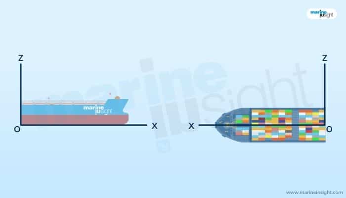
As we know from the basic knowledge of naval architecture studies, when a vessel heels or lists under the influence of external or internal causes about the longitudinal or x-axis, it comes under the domain of vertical transverse statical stability.
Likewise, all associated problems of dynamic or motion behaviour of a vessel about this x-axis or longitudinal axis are considered to be under the domain of seakeeping. The rolling motion of a vessel is the predominant aspect on which the entire studies of seakeeping are centred.
All studies related to the behaviour of the vessel about the z-axis or vertical axis can be considered under the domain of manoeuvring.
Similarly, all problems of the statical and dynamical behaviour of a vessel about the y-axis or transverse axis are known to be under the purview of longitudinal stability, both static and dynamic.
Trimming, or the significantly differential drafts along the length of a vessel, as shown, is a problem of static longitudinal stability. On the other hand, the pitching motions of a vessel are considered under the purview of dynamic.
The centre of Flotation of a vessel is intrinsically related to the longitudinal stability and response of a vessel. How?
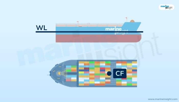
For this, we need to understand the concept of a waterplane.
A waterplane can be simply defined as the area formed or displaced by the floating body at the level of the waterline. Consider the figure below from both the side and top view. For the vessel floating at a definite draft of x above its baseline, it forms a certain waterplane at the waterline level that can be best visualized by looking at the plan view or the top view. Depending on the vessel design and the draft, the waterplane is highly variable.
The geometric centroid of a waterplane is known as the center of flotation.
Revisiting the simple lever theory
But the significance of the centre of flotation is much more than just a geometric centroid. It is essentially the point about which the physics of trim and also pitch (in the case of dynamical stability) can be entirely defined.
The transverse axis of action for response under longitudinal stability or behaviour is considered to be passing through this centre of flotation.
Hence, in other words, the centre of flotation can be explained as a certain point such that the transverse line passing through which a floating vessel can move or oscillate in the longitudinal sense (or along the x-z plane as per our convention).
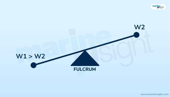
The physics of the centre of flotation can be best explained with the see-saw example.
When any two persons of dissimilar weight are seated on a seesaw, the side holding the heavier person goes down. Seesaws are directly based on the principle of a simple lever. The fulcrum is a hinge or the point about which the beam of the lever is pivoted. When any form of load or force is applied to either end of the beam, there is a moment created about this point.
In the typical seesaws we see in parks, this fulcrum is located at the centre point of the beam. Thus, from either end, the moment arm is the same.
Now what is a moment? Force times the distance. Since the distance is fixed in both cases, the resultant moment, which is the difference between the two counteracting moments acting from both ends, is dependent on the mass solely. Hence, a heavier person inevitably goes down first as he applies a higher load on one end of the lever and hence, creates a greater moment on his side.
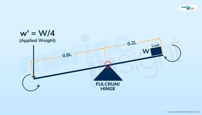
However, in most applications of levers as simple machines in the real world, the position of the fulcrum along the length of the beam is crucial. This is because, for the simple lever, the applied moment is the result of any form of load application. In the figure below, consider a simple beam of length L.
Consider the pivot point or the fulcrum to be situated at a distance of 0.8L from any one of the ends, say A.
The distance of this hinge from the other end B becomes equal to 0.2L.
Now, consider a body of weight W placed at end B. What is the moment induced?
In mathematical terms, it can be expressed as 0.2L X W. Now, for lifting this load, or in more physical terms, countering the induced moment, an equal and opposite moment must be created as per the first principles. Going by the equation for simple equilibrium, or equality of the balancing moments, we can say:
0.2L X W = 0.8L X w’
Where the left side of the equation defines the moment induced due to the load, and the right side denotes the balancing moment required to maintain mechanical equilibrium. 0.8L and 0.2L, as we know, represent the distances from both ends A and B to the pivot point or the location of the fulcrum, respectively; the weight W is placed at end B. w’ on the right-hand side of the equation represents load or force required to create the countering or balancing moment. Solving above, w’ comes out to be equal to W/4, or a quarter of the weight placed at the other end B.
Hence, we can say that the load or force required on the other side is much lesser than the originally placed weight to lift the latter itself, the difference at the moment or lever arms creating the required balance.
This is what is famously known as the mechanical advantage of a lever system. From simple day-to-day uses to complicated machines, this has been aiding mankind to lift loads universally.
In the above seesaw example, since the moment arms were equal, or in other words, the distances between points of application of the load to the point of action (the fulcrum or the hinge) were the same from either end, the weight plays the only determining factor for the net moment created.
The system is not in a state of balance, and the net moment is acted on the heavier person’s side, which is the product of the difference between the two weights and the equal moment arms.
A detailed description of the Centre of Flotation
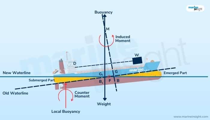
In the context of floating structures or bodies, the centre of flotation is the same as this fulcrum or hinge point. As shown in the vessel below, consider a weight W being shifted across a distance (d) from one point to another. This induces a moment W X d.
Now, from the physics of floating bodies, any form of imbalance of forces or loads is manifested in the form of changing drafts. Here, as the weight has shifted aftward, a moment is created in that direction, and the vessel tends to sink more in the aft as compared to the forward. This is known as trim by aft. Conversely, when it has a greater draft in the forward region due to higher sinkage, it is known as trim by forward.
Now, because of the weight shift, the longitudinal centre of gravity or LCG also shifts somewhat towards the load applied, the aft in this case (from G to G1).
Due to the sinkage on the aft end, the centre of buoyancy or LCB also shifts backwards accordingly (B to B1). From the nature of this effect, we can see that while some part in the aft has submerged, some part in the forward has risen.
By the law of physics related to the equivalence of the buoyancy required for the vessel to stay afloat, the part of the vessel immersed is volumetrically equal to the part of the vessel which has emerged.
A static equilibrium is attained when the new centres of buoyancy and gravity, that is, G1 and B1, are vertically colinear. As shown in the figure, consider two vertical projections through points B and G and B1 and G1, respectively. They intersect at a point M. This is known as the longitudinal metacentre, and that is constant for a given condition of trim.
From the transfer of moments for the given shift in weight w, we can say that:
GG1 X W = w X d
Where W is the displacement of the vessel, and GG1 is the shift in the vessel’s overall longitudinal centre of gravity as shown. Thus, the moment induced by the shift in the weight w is manifested by the trimming moment in the vessel given as W X GG1.
We do not go into the further detailed aspects of trim and stability as they are comprehensively explained in our other articles.
Now, going back to the nature of this trimming effect, we see that the waterline at this position is at an angle with the previous waterline (when the vessel was evenly floating) under conditions of equilibrium. These two waterlines intersect at a definite point F, as shown. This point, again, is nothing but the Centre of flotation. We also see that point F precisely marks the intersections of the immersed and emerged parts of the hull, as discussed above.
From the given case, for static equilibrium, due to the given shift in the weight afterwards, a countering moment is induced in a direction opposite to that of the induced moment. This is created by the buoyancy forces equal and opposite to the displacement of the submerged part, as shown.
Hence in our case, due to the shift in the weight, the counterclockwise moment created is balanced by the clockwise moment induced due to the buoyancy forces (B) acting on the immersed part of the submerged volume through its volumetric centroid, as shown.
The lever or moment arm is the distance between this centroid and the center of flotation, F, acting as the pivot. From a global point of view, the entire vessel experiences a trimming moment acting about the centre of flotation.
Similarly, the effect is the same when, instead of a change in loading, there is damage on the hull leading to ingress of water and thus a loss in buoyancy along with trimming if the breach is somewhere away from the midship. This essentially comes under the purview of damage stability.
On a dynamic scale, when the vessel goes into an oscillatory motion longitudinally about the transverse axis, it is said to pitch. This pitching action, where the forward and bottom ends of the vessel go up and down continually, is also acted upon this centre of flotation.
Thus, to conclude, the centre of flotation for a vessel is the point of action about which the vessel trims or pitches due to external or internal influences of loading. On a longitudinal scale, the centre of flotation is the same as that of the vertical centre of gravity on a transverse scale while dealing with problems of transverse statical or dynamic stability or seakeeping.
For a box-shaped vessel like a barge, the centre of flotation is on the waterline at midships in the way of the vessel’s centreline. However, for all practical purposes, based on the hull form of most vessels, the centre of flotation, which is the geometric centroid of a vessel’s waterplane at a given time, is slightly aft of the midship.
As there is no moment created when any form of force acts on the moment centre of any physical system (as the moment arm or lever is zero), the vessel just experiences linear sinkage when any form of loading or force is experienced in line with the vertical axis passing through the centre of flotation at any given point of time.
Under rough sea conditions, when the waterline changes very rapidly for a vessel, the centre of flotation varies highly.
The position of a vessel’s longitudinal centre of flotation is usually described as the linear distance from the aft perpendicular (AP), denoted as LCF. They are importantly used in longitudinal stability and motion calculations, forming a crucial part of a vessel’s hydrostatic data.
The Centre of flotation is also known as the tipping point or tipping centre.
You might also like to read-
- What is Rise Of Floor in Ships?
- What Are Vessel’s Particulars?
- What is Reserve Buoyancy in Ships?
- Port and Starboard Of Vessels Explained – Everything You Wanted To Know
Do you have info to share with us ? Suggest a correction

About Author
Subhodeep is a Naval Architecture and Ocean Engineering graduate. Interested in the intricacies of marine structures and goal-based design aspects, he is dedicated to sharing and propagation of common technical knowledge within this sector, which, at this very moment, requires a turnabout to flourish back to its old glory.


Latest Naval Arch Articles You Would Like:

Subscribe To Our Newsletters
By subscribing, you agree to our Privacy Policy and may receive occasional deal communications; you can unsubscribe anytime.