

Superstructure Of Ships: Bending Stress Distribution & Local Stresses
Based on the points explained in the previous article – Requirements for design & types of loads acting on the superstructure, the longitudinal bending stress distribution pattern is also another matter of interest.
Bending Stress Distribution for Ship Superstructure:
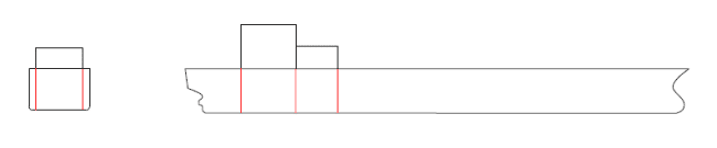
For long superstructures/deckhouses, the bending stress diagram shows a more or less linear pattern as both the former as well as the main hull simultaneously bend as a beam.
For short superstructures, there is a sharp disruption at the hull – superstructure interface in the main deck and the stress distribution line changes its direction.
Have you wondered why?
The reason is simple.
As you have seen above, the superstructure tries to bend away from the hull due to separation forces in case of short superstructures. This difference in bending sense creates the discontinuity in bending stress distribution with the stress being just equal at the deck interface. The slope of the stress line changes thereafter as in the green line of the following figure.
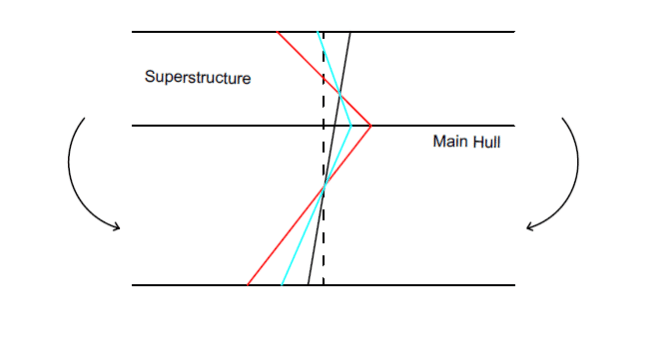
Coupled with this is the effect of stresses in the ends due to the discontinuity. If superstructure is short, the high bending flexural stresses occurring at the middle is propagated longitudinally and dissipates away at high values near the ends where there is an abrupt discontinuity. Thus, there is a tendency of transverse distortion as illustrated in the figure.
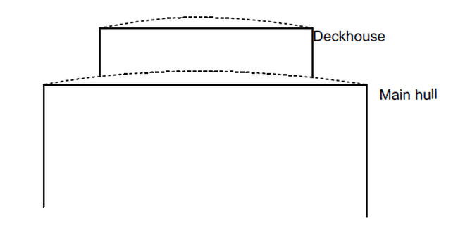
Superstructures and deckhouses also differ in a manner similar to longitudinal bending in case of transverse bending moments. In case of superstructures, which is in line with the deckside plating poses tends to bend in tandem with the main hull acting like a single beam with uniform bending loads, except for minimum ‘shear lag’ effects present by nature.
There is said to be no transverse distortion of the hull. On the other hand, if it is set inwards like a deckhouse, there is a disruption to the linear bending stress distribution. Complete load transfer also does not take place and the deckhouse tends to bend away separately from the hull with different curvature as shown. Hence, the interplay of the lengthwise and beam-wise arrangement of the deckhouse/superstructure causes profound effects in the event of longitudinal and transverse loading pertinent in the sea.
The position of the superstructure or deckhouse is also another crucial aspect. As we know, the hull girder acts like a simply supported beam to sea loads. So, considering the bending moment of a simply supported beam, the maximum bending moment acts in the middle.
Likewise, for the hull girder the maximum bending moment is present on the midship region. So, a superstructure present in the midship region will have a more pronounced effect of the above. For a long superstructure, high values of global bending stresses are generated in the middle whereas for a short superstructure the effect is acute all throughout (middle and the ends). If it is situated near the ends, mainly the aft like most of today’s cargo carriers these effects discussed above are very less pronounced. But, the structural discontinuity and stress concentrations are still a pressing issue for superstructures and needs to be taken care of for every ship for all general purposes.
However, longitudinal positions also do not affect the transverse behaviour of deckhouses or superstructures as discussed above.
From the above points, it can be stated that a long, full-width superstructure is lesser affected by loads than a lesser efficient, short deckhouse.
Classification guidelines define the regulations for the length of a superstructure with reference to its effectiveness. ABS rules dictate the length of the superstructure to be greater than 10% of the ship’s rule length to be effective for bending.
To summarize, we observe 2 aspects:
• If the superstructure is centred at or near midship, the bending loads directly affect the middle region. This is unavoidable if the operational design requires the position of the superstructure to be so. This cannot be rectified except for some concession in the material used or higher scantlings in the failure-prone zone.
• The vertical separation forces arise at the ends and are of greater importance. The condition is worse when the deckhouse is short, i.e. nearer to the midship due to predominantly high bending stresses, in turn triggering vertical separation and distorting forces and gradually decreases with length due to lesser intensity of global bending stress and low shear area.
• However, local stresses and discontinuities are inevitable except for an ‘ideal’ full length, full-width superstructure in continuum with the hull extents which is a rare case. Thus, proper protection and strengthening must be provided in the critical regions prone to high stresses.
Thus, we mainly focus on the last point and discuss the precautionary measures in the subsequent sections.
Structural Discontinuities And Local Stresses
One of the most indispensable aspects of superstructures and deckhouses is the problem of discontinuities. As already discussed in one of our previous articles, discontinuity is the sudden abruptness of a structural member. This is not conducive from the structural point of view as these create a path for the generation of local stresses. As discussed in one of our previous articles, there can be several discontinuities of a ship structure like a deck opening, ends of longitudinal girders and of course ends of superstructures.
A structural member design to withstand a certain amount of stress now has to withstand higher moduli of stress to the effect citing stress concentrations in those areas of discontinuities. These make them prone to failure or reduces the lifespan which adds up to jeopardizing the structural integrity of the ship. In ships involving such towering investments and more importantly, huge risk of life and property, these aspects are not desirable, are they?
Deckhouses or superstructures brought down to the deck level abruptly. Moreover, deckhouses are also not continuous with the side shell and are rather terminated inward of the side plating level. Also, often they are composed of different materials or even other breeds of steel with comparatively lesser modulus than the main hull. This creates large local stresses in its interface with the deck which propagate along the sides.
Reduction of Discontinuity- Induced Local Stresses
Although the principal discretion is upon the owner in terms of the requirements and also largely upon the designer in terms of optimizing his parameters, discontinuities are unavoidable in most of the cases. For instance, why would a ship-owner be insensible enough to spend more in making a superstructure extending all over the beam when his utility requirements are fulfilled by a narrower deckhouse itself? This would imply more material cost, unnecessary increase of deadweight and most importantly, time, which is more precious than money in the shipbuilding industry. Or for example, will the designer compromise the statutory requirements of the line of sight for the bridge to be placed atop a deckhouse for economising space to the side extremities for avoiding discontinuities? The answer is obviously a no. Thus, only preventive measures can be taken to avoid discontinuities where they are unavoidable.
However, some measures can be implemented to curb the effect of discontinuities due to superstructures and houses.
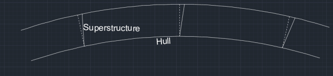
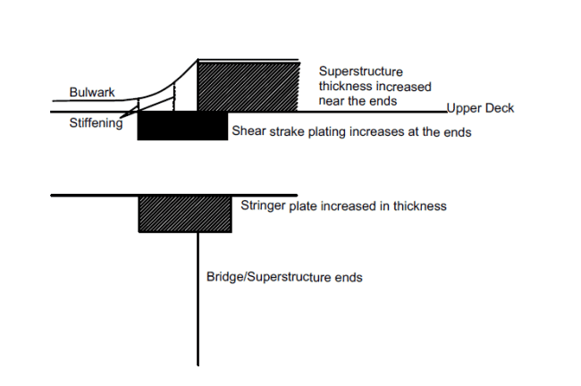
One of the foremost measures that need to be implemented is the construction of these house ends in line with bulkheads, both longitudinal and transverse. This is to maintain the continuity of the load path and reduce discontinuities as shown. Additional stiffening in the form of web frames or partial bulkheads is provided where there are large erections above bridge deck.
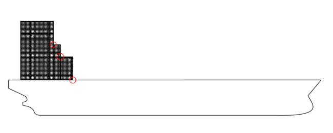
Often at superstructure ends, instead of abruptly ending it at the deck level, it is tapered or graded down. The scantlings of the superstructure are also increases in the sides and the ends.
Additional strengthening is provided by giving extra thickness to sheer strakes at the ends of superstructures and deck stringer plates. Typically, the former is increased by 50% and later by 25%. In case of short superstructures, where there are higher local stresses, the thickness increase for the above may be 20%.
Material Selection: Most of the materials used for ship superstructure are to withstand environmental stresses more than fluid stresses. To reduce the effect of stresses, the most readily available and conventional material is steel. However, one of the obvious drawbacks is the increase in steel weight.
Another reason is that whenever the section modulus of the hull and superstructure are of the same high value, there is a generation of high vertical ‘compatibility” loads to ensure maximum load transmission from the hull. Thus, this has an adverse effect and the purpose of using steel is defeated. If steel has to be used, high care has to be taken in choosing its properties and ensuring sound welding procedure at the interface. Otherwise, the common materials used are Aluminium and Fibre-Reinforced Plastic, owing to its low density, modulus but higher strength.
Carbon and glass fibre are also being widely used. Another very big advantage of using lightweight material is the need for lower ballast which yields lucrative benefits of higher payload. Modern designs are also seeing Aluminium blended with FRP composites as materials for use. High adherence to research and development in FRP is being given owing to its following advantages:
• Good fatigue properties
• Ease of moulding to shapes and forms to reduce discontinuities
• Good durability and lesser maintenance
• High load bearing capacities and less weight, as already discussed.
Superstructure Efficiency
Another crucial factor involved is the “superstructure efficiency”. The effectiveness of a good superstructure depends on the magnitude of load transfer taking place, remember?
Superstructure efficiency deals with exactly the same thing. The primary goal of a designer should be such that the superstructure/deckhouse takes up the same radius of curvature as the main hull under global loads. In other words, the “load-sharing pattern” of the superstructure must be compatible with the main hull girder in compliance to composite beam bending theory. One can never avoid longitudinal beam bending stresses, especially when the location is near midship, as discussed before. However, to curb separation forces and local stresses, which are detrimental to superstructure loading, one must aim for the maximum load-carrying capacity of the former with respect to the hull. Thus, superstructure efficiency is a measure of the load-bearing capacity of the superstructure or the magnitude of load transfer taking place from the main hull.
Superstructure Efficiency: Actual Load carried by the superstructure
Load carried if the superstructure were 100% efficient
Also, the other obvious guiding factor affecting superstructure efficiency is the attachment between the superstructure and the main hull. If there is a slip between this two entities, this comes at a heavy cost influencing both the local and global loads. For sufficient transfer of loads, there should be a sound connection between the hull and superstructure in the first place. To reduce separation force leading to bending in the opposite direction and ‘end distortions’, this is a must requirement. Earlier, riveting and bolting were very common. But this was not very effective and often yielded to low superstructure efficiencies. Subsequently, welding is now invariably followed in most ships.
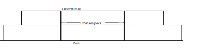
Sometimes, for long superstructure ships like passenger liners, there were problems of large longitudinal bending stresses. This meant the insufficient load-bearing ability of superstructure, implying unsatisfactory superstructure efficiencies. Remedial measures meant a better hull-superstructure connection, which was still under research and development or higher structural strength of the superstructure itself. The latter point involves higher scantlings leading to an unwanted increase in steel weight and was rejected. This lead to the concept of expansion joints. Here, the superstructure was segregated into multiple blocks or entities separated by a small gap. This gap was clumped by a joint and could accommodate expansion or contraction. The problems of large bending forces waned down considerably. However, on the contrary, expansion joints also created a problem of discontinuity and local stress at the same time. Thus, to satiate one issue, another issue took birth! In later phases, advanced welding techniques and proper material for superstructure reduced this problem to a large extent.
Over to you. Please comment for any doubts or suggestions.
Do you have info to share with us ? Suggest a correction

About Author
Subhodeep is a Naval Architecture and Ocean Engineering graduate. Interested in the intricacies of marine structures and goal-based design aspects, he is dedicated to sharing and propagation of common technical knowledge within this sector, which, at this very moment, requires a turnabout to flourish back to its old glory.


Latest Naval Arch Articles You Would Like:
Subscribe To Our Newsletters
By subscribing, you agree to our Privacy Policy and may receive occasional deal communications; you can unsubscribe anytime.
Can ships superstructure which are exposed to direct sun light, have insulation done by having ,”creeper screens” shieling sunlight rays Etc.
At Bridge wings Port and Stbd. can Green cover grass, z lawn be introduced. Similarly at Monkey Island surfaces Etc.
Next area where green grass covercis possible is at mast houses.
All ventilation fans draw supply air
Around funnel deck areas Etc..
Pl assess and comment
Thanks and Well wishes.
@Ajit: This can be done, however, they need to be secured properly as they are exposed to harsh weather and seas. Also, it will also depends on the company if they are willing to go extra for installation of the suggested modifications.