

Hull of a Ship – Understanding Design and Characteristics
The hull of a ship is the most notable structural entity of the ship. To define the hull, it can be said that it is the watertight enclosure of the ship, which protects the cargo, machinery, and accommodation spaces of the ship from the weather, flooding, and structural damage. But this alone does not suffice our requirements of understanding all the aspects of a ship’s hull.
In this article, we will see how the hull of a ship is designed for various factors taken into consideration during the entire lifetime of the ship, and how the design of a ship’s hull plays the most important role in the entire ship design and shipbuilding project.
Hull Related Nomenclature
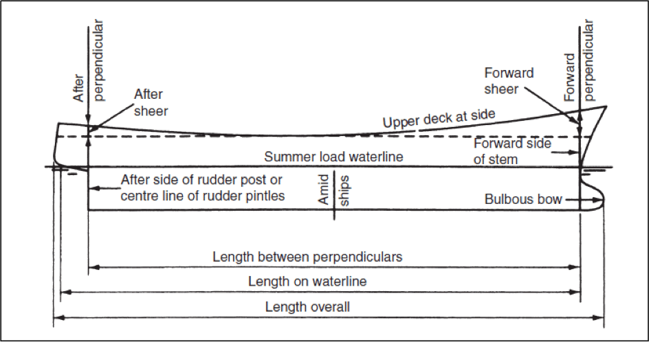
The above figure shows the schematic profile of a conventional ship’s hull. Understanding the meaning and applications of the nomenclatures related to it forms the basics of understanding ship design and shipbuilding technology.
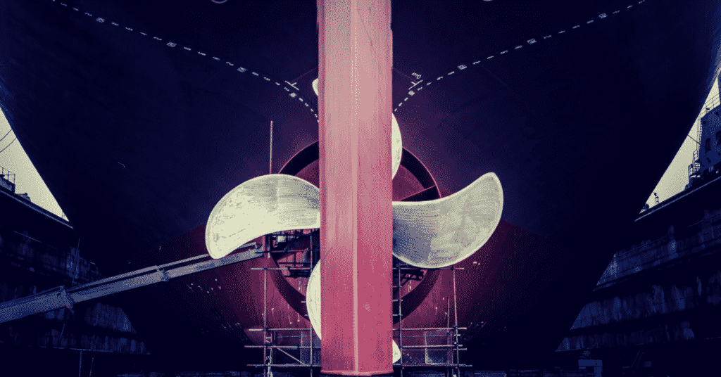
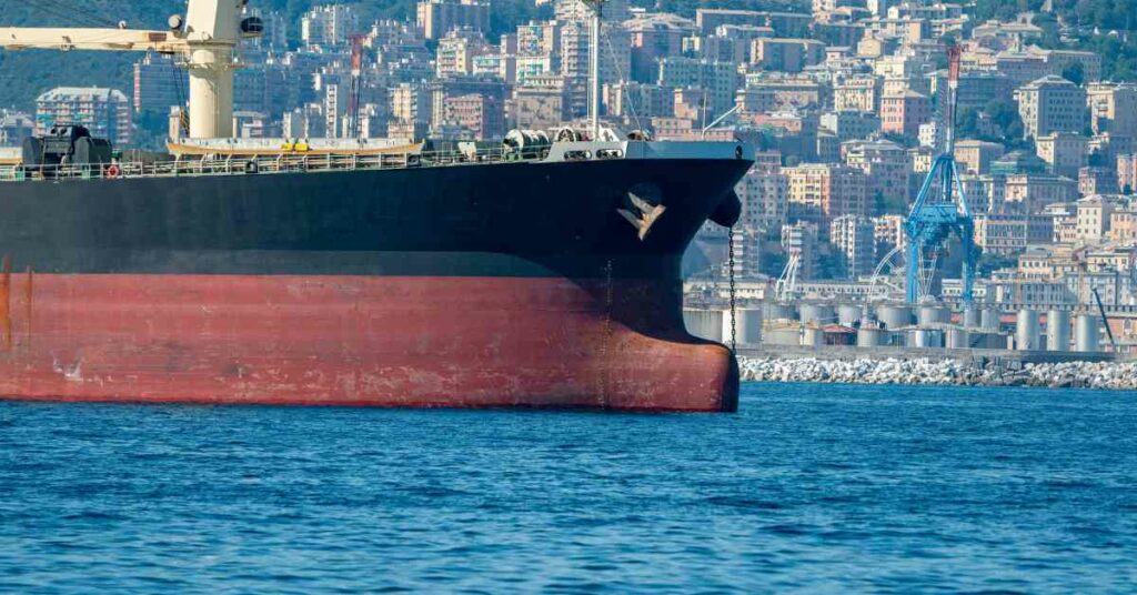
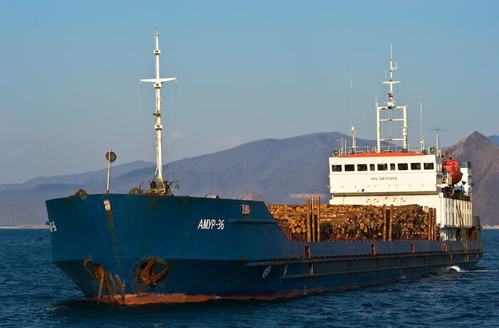
Bow and Stern: The forward most contour of the ship’s hull is called the bow, and the aft-most, its stern. The stem is the forward most contour part of the bow.
Forward Perpendicular: If a perpendicular is drawn at the point where the bow intersects the waterline, this imaginary perpendicular line is called the forward perpendicular. For most of the hydrostatic calculations, the forward perpendicular is used as the forward reference of the hull.
Aft Perpendicular: Depending on the designer, the aft perpendicular can be the perpendicular drawn through the aft side of the rudder post or through the center-line of the rudder pintles. The aft perpendicular is the aft reference line for all hydrostatic calculations.
Length between Perpendiculars: The length between the forward and aft perpendiculars is the length between perpendiculars. The LBP is a very important parameter in all stability calculations, hence calculation of the LBP at various drafts becomes an important step in carrying out stability analyses.
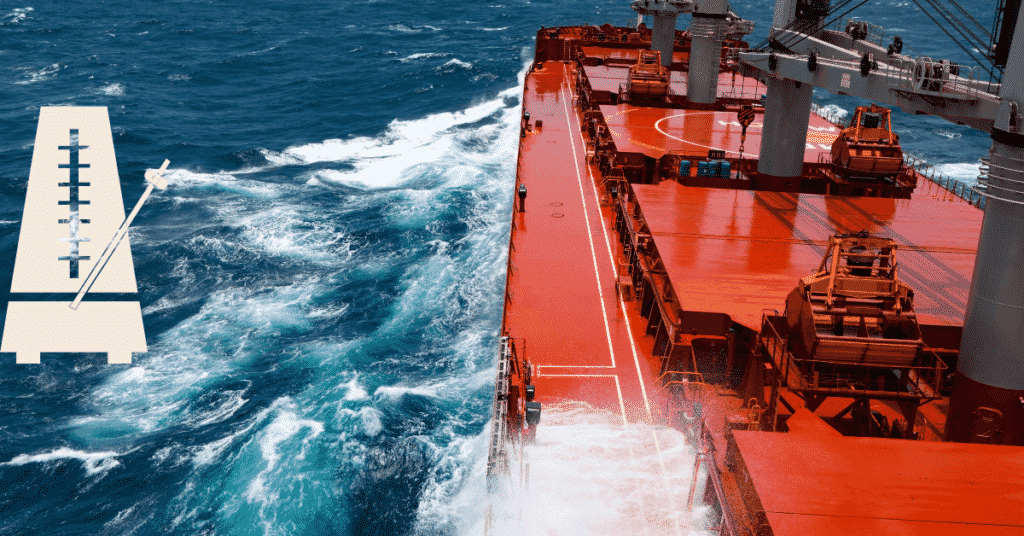
Sheer: The upward curve formed by the main deck with reference to the level of the deck at the midship, is called sheer. It is usually given to allow flow of green water from the forward and aft ends to the midship and allow drainage to the bilges. The forward sheer is usually more than the aft sheer to protect the forward anchoring machinery from the waves.
Summer Load Line: The summer load line is the waterline of the ship at sea water when it is at its design weight and ballast conditions. It is also called the design draft; this forms the reference for all other load lines of the ship.
Length of Waterline: The length of the ship’s hull at the summer load line is the length of waterline for the ship. This length plays an important role in the calculation of hydrostatics of the ship, as well as propeller design calculations.
Length Overall: The length between the forward-most and aft-most point of the ship’s hull is its overall length. This length plays a major role in designing the docking and undocking plans of the ship. In shipyards where multiple building docks are available, the overall length, beam, and depth of the ship is a deciding factor in choosing a suitable building block for the ship.
Hull Lines and Shape
The first step in designing a hull of a ship is designing its shape and form. The form of the ship’s hull is estimated by means of various form coefficients, discussed as follows:
Block Coefficient: Block coefficient is the ratio of the ship’s underwater volume to the volume of the imaginary rectangle enclosing the underwater portion of the hull. Since the length, breadth, and height of this enclosing rectangle would be the length between perpendiculars, Maximum Beam, and Draft of the ship, the block coefficient is expressed as follows:

The value of block coefficient is one for a ship with the rectangular cross-section. Hence, for a typical ship’s hull form, it would be less than one. The higher the block coefficient, the fuller is the hull form (e.g. oil tankers, bulk carriers). Finer hull-forms have lower block coefficients (e.g. container ships, warships).
Midship Coefficient: The midship coefficient is the ratio of the submerged area of the midship section to the enclosing rectangle. It is hence expressed as:

There are a number of other form coefficients like prismatic Coefficient, Volumetric Coefficient, etc. which are basically the parameters used to define the volumetric distribution of the ship’s hull along its length. Once these coefficients are arrived at, from statistical studies, the hull lines are developed.
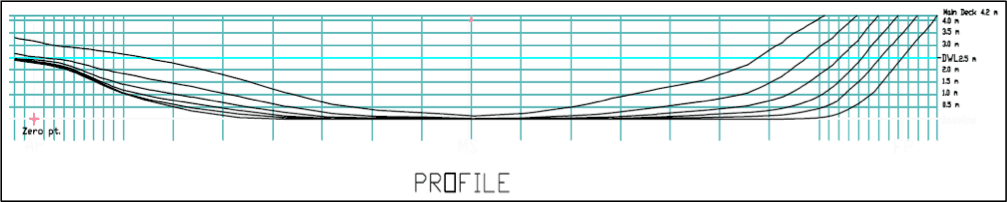
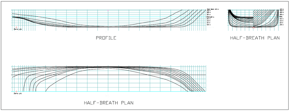
The lines plan of a ship’s hull comprises of three views. To understand the lines plan, we first need to know what are buttocks and waterlines.
When the hull of a ship is cut into multiple sections longitudinally, that is, if you slice the ship’s hull at every two meters starting from port to starboard, you would produce longitudinal sections at every two meters. The contour of each longitudinal section is called a buttock line, and this is exactly what is represented in the profile plan, as shown below. The reference lines for the profile view are the stations (vertical grid lines, which denote the longitudinal position) and waterlines (horizontal lines, which denote vertical positions).
If the ship’s hull is sliced along each waterline, then every waterline produces a distinct curve. Since a ship’s hull is symmetric about the centerline, a common practice prevails in which the curve is drawn on either side of the centerline, and this view is called the body plan or the half breadth plan of the ship.
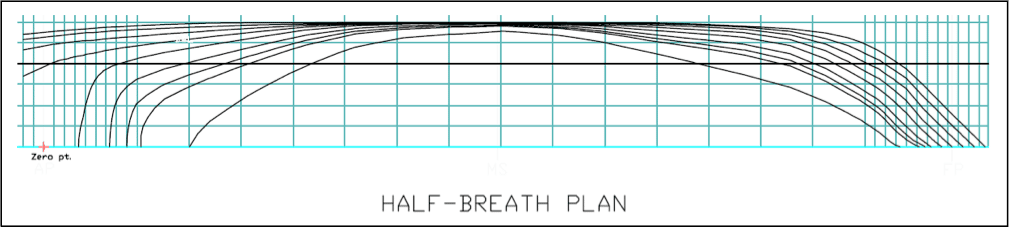
Important Tip: The shape of the waterlines (in the half breadth plan) play a deciding role in the shape of the stern and the efficiency of the propeller. In the above figure, the waterlines move away from the ship’s centerline with the increase in height above baseline. That is, the innermost curve is the lowermost waterline. Take note of how the waterlines straighten at the aft as we move upward from the keel. This shows that the ship has a transom stern. So why is transom stern preferred? The answer lies in the shape of the waterlines at the stern. The longitudinal direction was taken by the waterlines at the stern ensure the flow of water at the stern in a direction almost perpendicular to the propeller disc. This ensures minimum crossflow at the propeller, therefore ensuring maximum propeller efficiency.
If the ship’s hull is sliced to form a section at every station, we obtain the body plan, as shown below. The typical practice of drawing the body plan is to denote all the half sections (due to the hull’s symmetricity). The sections forward of the midship are drawn on the right side of the center line, and all the sections from the midship to the stern are drawn on the left side.
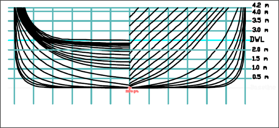
The body plan is the most useful representation of the ship’s hull lines. The reference lines in the body plan are the buttocks (vertical grid-lines), and the waterlines (horizontal grid lines). The body plan, along with the reference lines can be self sufficiently used to develop the profile plan and half breadth plan of the ship. It is also useful in developing the sectional area curve, and bonjean curves of the ship.
The complete lines plan of a ship is arranged by placing the profile view on top, with the half breadth plan just below it, and the body plan to its right, as shown below. The lines plan provides for the foundation of developing not only the three-dimensional hull model, but also developing frame-wise structural drawings, general arrangement, and loft drawings at the shipyard.
Hull Structure and Strength
The structural design of the hull of a ship amounts to approximately 70 percent of the total structural design of the ship. The stages in designing the hull structure are as follows:
Step 1: Calculation of Loads on the Hull: This is where the classification society rules come into play. Rulebooks have specialized formulae for calculation of wave loads on the ship’s hull. The still water bending moment, wave bending moment, and shear forces are to be calculated using these formulae. These load values act as set points in the entire structural design process.
Step 2: Scantling Calculations for Midship: The dimensions of all the structural members of the ship (plates, stiffeners, girders, beams, pillars, etc.) are collectively called scantlings. The loads calculated in Step 1 are used to arrive at the scantlings, and this is calculated for structural members at every frame.
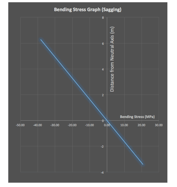
Step 3: Midship Section Modulus: The midship section structural drawing is prepared according to the calculated scantlings. This is followed by locating the neutral axis of the midship section and calculating the section modulus of the midship section. Two criteria are to be satisfied at this stage:
- The obtained midship section must be equal to or more than the minimum section modulus value obtained by the empirical formula in the rule book.
- The bending stress at the deck and the keel are calculated, and it is checked if the stress values are within the required factor of safety.
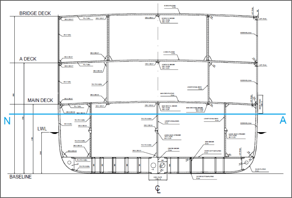
In the above midship section drawing, the blue line (NA) is the neutral axis of the section. The bending stress graph is drawn with the neutral axis with the reference (origin), and the top-most and lowermost ends of the graph would denote the stress values at the deck and keel respectively, as shown in the stress graph below.
Why do you think it is important to design the structure of the midship section of the ship before any other sections? Read this article to find out what makes midship the structurally most important region of the ship.
Step 4: Frame-wise Scantling Calculation: Once the midship scantlings satisfy the criteria, the scantlings for structural members at each frame are calculated, and corresponding frame-wise structural drawings are prepared. Special formulae are applied for the forward and aft sections, and bulkheads, and drawings are prepared for the same.
Step 5: Calculation of Steel Weight: The obtained scantlings are the used to calculate the steel weight of the ship. This is where the iteration begins. If the calculated steel weight lies outside the empirically and statistically obtained values, the designer might have to look at using lighter weight steel at suitable regions or take other decisions to keep the lightship weight within limits.
Step 6: Development of 3D Structural Model and FEA Analyses: With the structural drawings at each frame, a three dimensional structural model is prepared for the entire hull. This process takes the longest time because the accuracy of this model would directly impact the results of the finite element analyses that are to follow. Three-dimensional meshing is carried out on the 3D model, followed by finite element analyses for various conditions. It is based on the results of these analyses that classification societies today approve a ship’s structural design, as they produce more reliable data than those produced by linear calculations.
Course Stability of the Hull
The other important aspect of the ship’s hull is its directional or course-keeping performance at sea. In other words, its manoeuvrability. In order to evaluate the manoeuvrability of the bare hull, we evaluate the following aspects:
- Straight Line Stability: If a ship moving in a straight line is subjected to an external disturbance, and it changes its direction but continues to move in a straight line along the new direction, without the help of the rudder, then the hull is said to have straight-line stability.
- Directional Stability: If a ship moving in a straight line is subjected to an external disturbance, and it continues to move along a new path which is parallel to the initial direction, the ship is said to possess directional stability. Directional stability is not possible without the aid of a control surface (e.g. rudder), but having straight-line stability makes it easy to attain directional stability.
- Path Stability: If a ship moving in a straight line is disturbed externally, and it continues to move along the same path (after a few oscillations), it is said to have path stability. Path stability, like directional stability, can only be attained if straight-line stability is achieved.
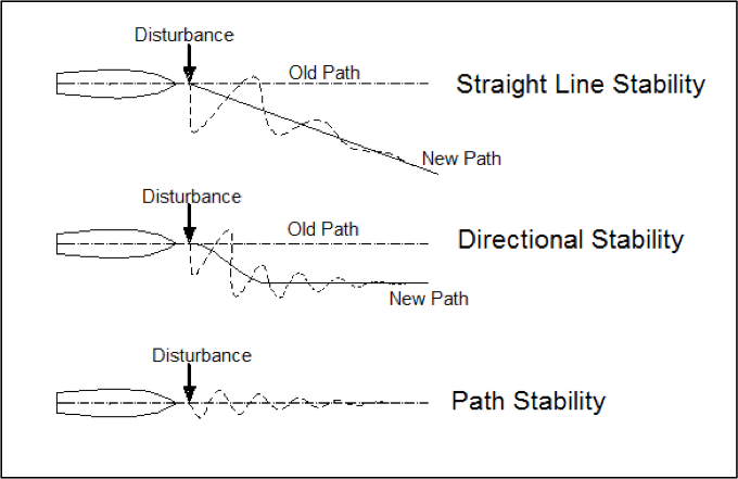
The design goal during the development of a ship’s hull, is, therefore, to attain straight line stability. For this various tank, tests are carried out at model basins and the hydrodynamic coefficients are measured for the bare hull. These hydrodynamic coefficients are the characteristic properties of the hull’s course keeping abilities, and in case of unwanted results, changes in the hull’s shape or geometry are decided upon. For example, a skeg is often added to the hull in later stages of design to improve on its straight line stability, after the model basin test results are obtained.
Hull-Superstructure Interaction
It has been observed that the presence of a superstructure on the main deck reduces the bending stress at the deck from the stress value predicted by the beam bending theory. This is because of the interaction of the shear stresses with the bending stress at the ends of the superstructures. However, this leads to deformations at the superstructure ends. So, in other words, if a superstructure is an efficient one, is must be able to absorb a certain portion of the bending stress at the deck. The extent to which it takes up the bending stress determines its efficiency, which comes designers prefer to call Superstructure Efficiency. It can be expressed as:

It depends on the designer whether to design a superstructure that would take up the bending stress from the hull, or whether to design one that is free from any interaction with the hull. Designing a 100 percent efficient superstructure would be possible, but would come at the cost of heavy weight deep bulkheads at the superstructure ends to prevent severe distortions due to shear. However, to increase the superstructure efficiency, most ships have superstructures connected to the hull by means of bulkheads transverse bulkheads under the deck, and webs that run continuously from the hull to the superstructures at its forward and aft ends.
Other Aspects of a Ship’s Hull Design
There are other aspects of a ship’s hull that play a major role in the performance of the ship at sea. Calculation of bare hull resistance is an important step in determining the energy efficiency of the hull. Methods to calculate the bare hull resistance have been discussed in detail in this article.
Another vital aspect of the ship’s hull is its watertight integrity. To ensure this, the designer must ensure the intact and damaged stability of the ship. To know about the stability aspects of a ship’s hull, you are advised to read the articles on intact stability and damaged stability of a ship. The article on subdivision of a ship’s hull discusses how the number and position of watertight bulkheads are decided during the design of a ship’s hull.
Vibration and dynamic response of the ship’s hull is a factor that determines not only the performance of the ship but also its longevity at sea. Out of all the different vibrations on a ship, vibration of a ship’s hull girder is of major concern. A ship with unwanted levels of vibration could possibly be a scrapped project right in its initial years. Read this article to know more about the types of vibrations on a ship’s hull, the sources of excitation, and design measures taken to minimize the level of hull vibrations on board.
Disclaimer: The authors’ views expressed in this article do not necessarily reflect the views of Marine Insight. Data and charts, if used, in the article have been sourced from available information and have not been authenticated by any statutory authority. The author and Marine Insight do not claim it to be accurate nor accept any responsibility for the same. The views constitute only the opinions and do not constitute any guidelines or recommendation on any course of action to be followed by the reader.
The article or images cannot be reproduced, copied, shared or used in any form without the permission of the author and Marine Insight.
Do you have info to share with us ? Suggest a correction


Latest Naval Arch Articles You Would Like:

Subscribe To Our Newsletters
By subscribing, you agree to our Privacy Policy and may receive occasional deal communications; you can unsubscribe anytime.
What is the ship’s six degree of rotations ? Please explain with graphical representation.
Explain about Ship’s Six degree of rotation with graphical representation.
same as an aircraft (it’s easier to find graphical representations). Roll (port-starboard lean), pitch (fore-aft vertical movement), yaw (port-starboard turn, or horizontal movement)
Dear Sir
I’m QA Engineer trying to organize PPT Presentation for New QC Team joined our Shipyard to familiarize with various ships/vessels and platforms Hull and main components.
Appreciate if you can lend your help.
Thanks
Ganesan
Singapore
Representing the ship’s body in a system of immobile coordinates (Oxyz), exist 6 degree of liberty, in witch the vessel will move only in flotation stage, as follow:
a)- 3 translation moves on the axis X;Y;Z,
b)- 3 rotation moves on the axis X;Y;Z, noted as (x); (y) and (z).
Considering movements (X);(Y) and (Z), observe that vessel is in indifferent equilibrium, because:
– around axis (Z) is vertical move which represent medium draught variation, and a rotation move which represent the ship’s gyration; situation of stable equilibrium;
-around axis (X) and (Y) are manifesting the pitching and rolling moves, when the ship is in unstable equilibrium.
For the students of the first year of teaching? Too narrow point of view///^(
Hi sir.
I need resources for research about fore and aft bodies plane.
Could you help me please?
Thanks
Mehrdad
Iran
Hi could you please update the figure 5 replacing the right picture title with “body plan” instead of “half breath plan”.
Thanks.
frame numbering of structure how to name aft of aftwe-perpendiculer
Thank you Sir for sharing your quite obvious passion of ships.