

Different Technologies To Measure Hull Stresses In Ships
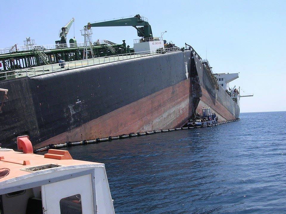
Hull stresses in ships require additional attention, especially considering the catastrophic consequences which are possible as a result of their failure. We often hear of midship failures, failure resulting from racking distortion in Ro-Ro and container ships.
Today ship design has reached a stage where the structures are evaluated for reliability using the simulation modules of different finite element analysis (FEA) programs. This is used in conjunction with rules laid down by the classification societies, and a certain factor of safety in design is what guarantees the ship for use during its operational life.
The design trends have changed over the years, we can see a shift from the reliance on formulae based applications obtained from first principles (with their empirical modification) to more advanced analysis using these software packages. The basic reason being that these allow more flexibility to the designer. Previous assumptions which were employed because of lack of computational power in early days of development are now being taken to task by today’s enormous advance in computing.
The rule based design is called Level I design, and design by analysis is called Level II design. Today, we are somewhere in between Level I and II. The next big step would be performance based design (Level III) and to fuel this change, we require a lot of background study, and the technologies discussed in this article will serve towards realising that change.
Although, numerical quantification exists to describe the hull bending moments, still-water and wave induced shearing and bending forces; the major design firms and classification societies still have very few data or quantification available for different load combinations in different sea states, at different Beaufort Scales along different trade routes. As result of this, it becomes impossible to predict the response of the ship hull to the environment when on voyage.
It is therefore important to gather a large pool of statistical data based on which we can develop empirical relationships to directly predict hull stresses of a ship for a given sea state and route. Let us take a look at the different technologies which would enable us to gather this valuable data:
Strain Gauges
Strain gauges are the oldest among the technologies to measure hull stresses. These make use of calibrated devices that express the stress upon the sample in terms of the strain induced on it.
Strain gauges are commonly of the foil (electro-resistive) type, although new technology is at hand these days, sometimes providing better accuracy. Basically categorising them in terms of application, they may be:
- Short baseline (for < 1 inch long samples)
- Long baseline ( for 2m long samples along the sample stress axis)
- Derived as per location (e.g. hull girder bending moment / stress using motion sensing)
- The new technological development not yet under commercial production.
Short baseline gauges are excellent for measuring shear stresses, along with their low cost, and ability to be installed in small places (measuring ¼ th of an inch). They are ideal for stresses at ‘hotspots’. The gauge matrix is safe for operation in explosive atmospheres by virtue of their small voltages. Disadvantages include directional accuracy and temperature errors.
Long baseline gauges are used for hull girder stress measurements on commercial ships. The relative accuracy of their operation depends on how closely they resemble uniaxial members. This means they cannot be subjected to secondary stresses (stresses arising as a result of internal adjustments in strain and not because of loading). These devices use potentiometers (cheap, limited life), transformers (longer life) or transducers (larger life, expensive).
Derived moment and stress calculations are done using motion sensors in combination with calculated response characteristics. These are location specific but have not cleared the requirements of some classification societies.
New technology has now found its way into application onboard ships, some examples in stress measurement include fibre optics, acoustic, radio, LASERs etc.
Fibre Optic
Fibre optic strain gauges have been developed and deployed, they are inexpensive but the cost of their coupling is quite high and beyond the current expenditure trends. Their reliability is also a big concern. But, they may just develop a niche in military applications, explosive environments, composites and low weight applications etc.
Acoustic
Acoustic strain gauges are capable of operating without direct contact. These have been traditionally used for bridges, but we might see them being extended to ships one day. Advantages include the ability to penetrate paint, rust and other surface obstructions. Although they have to be economically viable for onboard application besides calibration.
Laser / RADAR Ranging
The application of these to ship hull structures have their own advantages and disadvantages. If applied, they would need to be operated using shorter wavelengths offering higher accuracy which would obviously come at a cost- both price and power consumption. These are susceptible to errors from environmental conditions like atmospheric moisture when operated at short wavelengths.
Motion Based Stress Monitoring
This method is quite the topic of research today, with emphasis laid upon racking stresses resulting from roll / sway motions in ships. Real time motion measurements are taken during voyage and compared with predicted response according to finite element analysis. Results generally show good co-relation with derived measurements. This method would aid several procedures and decision making during voyage. It also complement the iterative design process.
Fatigue Damage Sensors (FDS)
Used to estimate the fatigue life of ship structural member subjected to wave loads and other forms of loading from the marine environment. These are sometimes similar in size and integration to strain gauges and are often used in conjunction. The sensor reacts to the strains in a structure and this strain causes cracking in it. The length of the crack is in direct relation with the fatigue life. Currently this technology is being verified for accuracy by comparison with conventional fatigue assessment methods.
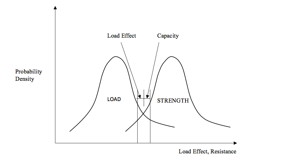
Data Analysis and application
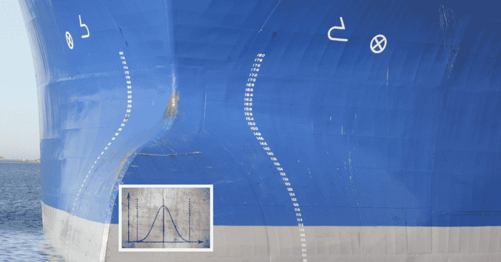
Having developed the tools for data collection, there arises the need to develop the statistical background. Once a large pool of data is available for various hull plate and girder stresses at various sea and wind conditions operating at various sea routes, it would be possible to develop direct empirical relations for hull stresses using the environmental and structural factors. Classification societies have taken this initiative to develop rules and guides for the same. Here in this graph, it is shown how the strength and loading vary as probability density function over a given range. What is interesting to note is the region between the curves (mentioned as capacity in the graph) where the structural strength exceeds the load effect. This is the region of interest to a structural designer, which he would look to maximise. This is the region of maximum structural reliability. The loading conditions, both isolated (one dimensional) and a combination, are necessary to study the effects on the hull structure.
This would set the stage for Level III design where the accidental loads and risks involved (Often called Risk based Design) could be pre-evaluated before a certain sea route is undertaken. This would be a boon for the ship crew who have to take the call in rough seas. Further accidents involving major failure of hull structure can be avoided.
Data analysis techniques like neural network programmes can especially come handy in obtaining meaningful data from a statistics. The next big step or Level IV design is when the above concepts can be applied to loading combinations. The graph as shown earlier would take 3-dimensional form with an additional axis taking care of any component of the combined stresses like torsion, bending, axial etc.
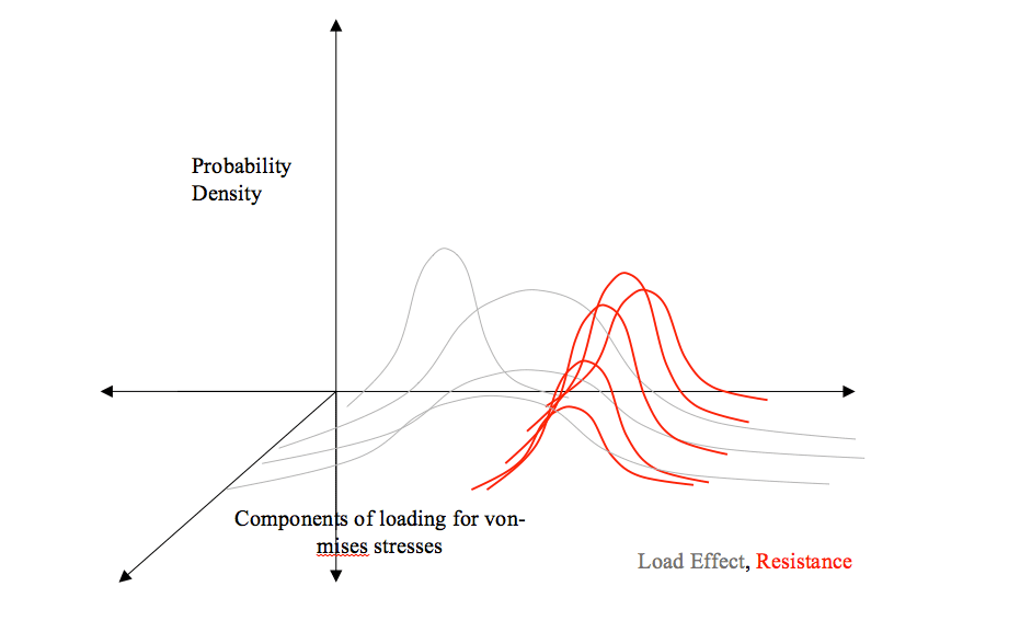
This can be extended for other loading combinations (additional axes) and so a 2-D surface would be obtained. Any point on this surface would give the probability of a ship hull failing or surviving against an eventuality. All of this to ensure that ships are better and safer at sea.
Do you have info to share with us ? Suggest a correction


Latest Naval Arch Articles You Would Like:

Subscribe To Our Newsletters
By subscribing, you agree to our Privacy Policy and may receive occasional deal communications; you can unsubscribe anytime.