

Understanding Ship Model Testing – Construction & Types Of Facilities
As contrary to large scale unitised mass production like motorbikes or cell phones, mega machines such as ships involve rigorous vigil at each and every point of construction, starting from the design phase to the ship launching phase.
As ship design and construction are time-consuming and tedious processes, various errors and inaccuracies are assessed right from the very early stages, by taking precautions and tests at each and every step.
It is for this reason that ship model testing plays a pivotal role right from the basic design stages of a pre-constructed ship. The purpose or the need for ship modeling is explanatory in its name itself; wherein a large object such as a floating vessel can be assessed on a miniature scale, allowing visualising of a ship’s behavior and other physical characteristics before the commencement of ship construction.
Not only for ship designers, but even in vast research and development field of naval architecture or ocean engineering studies, model tests are crucial for study of waterborne structure such as offshore rigs, oil platforms, oil wells, floating harbours or jetties, etc. In recent times, the emergence of ship design software and other path-breaking simulation systems have eased the complexities of manual model testing operations to a considerable extent. However, the significance of physically testing a model still remains as even the software-based approaches have their limitations and often rely on the empirical relations established through physical tests.
Purpose of Ship Model Testing
Now let us have a brief listing of the purpose of model testing:
- An estimation of the hull form, form parameters, and basic curvature
- Main dimensions on a reduced scale
- Stability Characteristics on a rough scale
- Seakeeping and Maneuvering Characteristics
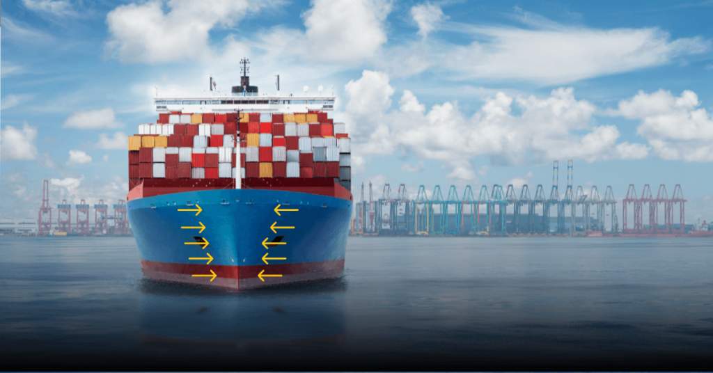
- Resistance Tests
- Propulsion and powering
One of the very big advantages of having a ship model is that it can scale down all the dimensions of the ship to a reduced scale such that all the important parameters of the prototype can be estimated and analysed on a model scale and eventually extrapolated to the full scale.
For example, in resistance experiments, the encountered resistance on the ship model in a towing tank can be used to estimate the feasible resistance value of the corresponding main ship in a seaway, thanks to empirical relations.
However, there are certain disadvantages as well. Model testing cannot be used to predict detailed design aspects of a vessel such as general arrangement, capacities and tankage, detailed structure, subdivision, freeboard and so on.
Moreover, model testing fails to render the exact response of the ship in worse case scenarios, which are pretty common at high seas. It also has a lower degree of accuracy as compared to modern software-based methods and can be prone to errors.
Nonetheless, ship model testing is considered one of the crucial preliminary phases of ship design and research which has gained significance worldwide.
Making A Ship Model
Needless to say, making a ship model is quite a tedious job that requires precision. However, much like the ship, modern CAD/CAM techniques have eased things a lot. Though the time taken to make a model is negligible as compared to the real ship, of course, still almost many of the basic aspects are taken care of during the construction phase like:
- Model Dimensions
- Proper lines and hull form
- Significant ratios (length/breadth, breadth/draft etc.)
- Hull configuration
- Position of centres of gravity and buoyancy
- Primary loading of ship model
- Moments of Inertia
- Appendages (if any)
- Motor type (for a powered model)
- Propeller and propulsion arrangement ( for a powered model)
What are the Ship Models made up of?
Now the question arises, what are the ship models made up of?
Of course, ship models are not made up of the same material as that of the main ship, i.e. mild steel or high strength steel. The reasons are quite simple.
Firstly, an organization, institution or individual conducting a model experiment would not want to undergo the inconvenience of procuring the material required to make the ship model in a meagre amount from a steel plant, making them in mass production.
The next problem is that making ship model from steel sheets or plates require very precise workmanship and also equipment available only in shipyards.
The third problem is the weight-buoyancy distribution itself. The materials making the main ship are quite bulky. Hence, from the physics of flotation itself, the buoyancy required to keep a body upright in water is dependent on the displaced volume.
Now as these ship models are generally small-sized, they would not have the desired waterplane area and the volume required to cater to the displacement and hence would sink due to their own weight.
Thus, models are mostly made up of:
- Wood
- Wax/Paraffin
- Plastics (FRP, GRP, fiberglass etc.)
- Lightweight metals such as cast lead or tin sheets
- Special types of paper
Wood was used for making ship models in the early days, but now it’s rarely used. This is because despite being durable and hard, extra scantlings (thickness, girth etc.) were required to give it additional strength.
This gave little space for ballasting/deballasting procedures. Furthermore, wood was found to expand and swell during continued flotation, leading to significant changes in weight. Having said that, even wax/paraffin had its own disadvantages of low strength and gradual distortions.
Therefore, for this reason, plastic fabric and fibre materials made their advent like GRP( Glass Reinforced Plastics) and Polystyrene. This allowed all the qualities of required strength and stiffness of ship models without compromising on the weight.
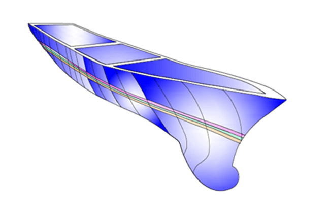
The method of Ship model manufacturing is also quite interesting. A plug is first made similar to the exact shape of the vessel with the help of media such as paraffin or wax.
This is termed the ‘negative model’. The plug is then coated with a release agent. A female mould is built up around this with layers of fibres impregnated in the resin. When the resin dries, the two temporary moulds are separated.
The inside of the female mould is then coated with the release agent and the layers of fibre/fabric are concentrated on the outside to give the final finish. The finished hull is then carefully separated out and is sent for fitting. This female mould can then act as a blueprint giving rise to as many ship models as required.
The exact hull fairness and proper definition of lines can be done with the help of a milling machine.
This process requires hydrostatic calculations which are done prior to the model-building stage. Great care is taken while moulding the model as small errors and imperfections can drastically alter the ship design which in turn could fail its purpose itself.
The latest high-end computation techniques have made the purpose of ship model making easier, much like the mainstream shipbuilding industry itself!
It is needless to delve into the types of ship models as they are mostly scalped in the form of the main ship types, viz., bulk carriers, tankers, barges etc. Sometimes, these models are simply carved out in a simple boat like form where only the resistance, propulsive and basic hydrostatic calculations are of interest.
Ship Model Testing Facilities
The types of facilities for ship model tests are based on the objective of an experiment to be done. Needless to say, all model scale experiments are done in freshwater spaces of different forms and dimensions.
TOWING TANK: It is the most commonly seen facility for the testing of models. Towing tank is like a shallow depth elongated swimming pool (in the order of around 100 meters). The girth is limited, mainly based on the breadth of the models. This long and narrow channel of enclosed freshwater is employed for a variety of experiments where the model is needed to be ‘run’ or driving through some distance without giving the transverse motions much importance.
Most of the crucial parameters such as resistance, propulsive power and its associated parameters, displacement measurements, propeller immersion, trim, speeds, engine/ motor performance etc. are measured through this test.
As breadth is the prime restriction in towing tanks, all those experiments where the transverse motions of the ship are associated, are avoided. Most of the manoeuvring and some of the seakeeping-based experiments are thus done on wider basins and flumes instead of narrow towing tanks.
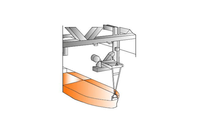
The ship model is generally attached to a carriage. This carriage is more or less like a moveable platform that moves on rails provided at the sides of the tank in tandem with the model motion.
The carriage apart from supporting the model also serves various other purposes such as housing crucial recording instruments, computers and other data collection systems. We will discuss more the instrumentation in experiments in the upcoming articles. Moreover, experimenters and observers can also mount the carriage and remain a witness to the experiment.
Another crucial factor occurrent in towing tanks is shallow water and blockage effects. Though we will not delve deeper into this intriguing concept, it may be worthwhile to say that due to the shallow depth and most importantly the narrow breath, the model surges in very constricted conditions. The problem is further aggravated if the model is bigger.
Due to the meagre gap between the model surface and the surrounding physical boundaries (at sides), the flow of water is altered. This adversely affects the hydrodynamics associated with the floating body.
At the end result, the resistance increases hindering the smooth velocity of the model. The problem can be better understood at a higher level of ship hydrodynamics.
MODEL BASIN: This facility is somewhat different from the towing tank in terms of the girth which is comparatively larger. Thus the width and length are of comparable magnitude. The depth, however, remains more or less the same (around an average of 10 meters, commonly).
Since the girth is wider here, the ship is unconstrained to perform all the six degrees of its motion. So, this physical basin is utilised to perform seakeeping tests like roll decay, heaving or other manoeuvring experiments such as zig-zag, spiral or turning circle, which would not have been accomplished in a narrow towing tank. Other applications also include testing offshore structures, mooring systems, and pipelines.
In many of the ship model basins, a re-creation of a feasible oceanic environment can be completely created with the generation of winds, waves, and currents. One very significant advantage of model basins is that three-dimensional waves can be generated and that too, in all directions, creating a scenario similar to oceans. The wave generators and absorbers are accordingly placed.
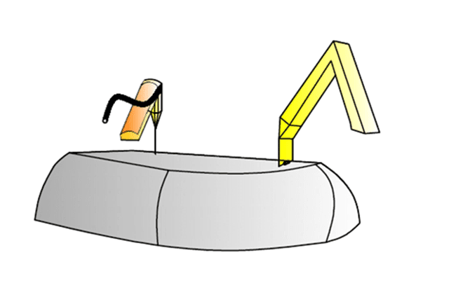
This arrangement is different from a towing tank. Here, the model is moved and rotated with the help of an arm which extends up to more than half the span of the tank. The wave generator and the absorber are always placed opposite to each other.
WAVE FLUMES: Wave flumes made their advent during later stages when approaching a more ‘realistic’ simulation gained significance. Here realistic means creating the model testing environment similar to actual sea states undergone by the ship.
Physically, a flume resembles a towing tank. Here also, the length exceeds the width which significantly exceeds the width. Also, the depth is not much, though can be more than a simple towing tank. Another interesting feature of a flume is a deep pit somewhere middle of its length. The depth of this pit is quite high and is created for technical reasons. The main idea behind this is to recreate an oceanic topography where there can be varying depths of the ocean bed, ranging from low depths to depths of around 10000 feet or above.
A distinguishing feature of wave flumes is the wave generators. These systems generate depths of varying wavelengths, frequencies and of course, heights. Now, the question arises, how do we generate waves? The answer can be simple:
- Wind
- Creating pressure variations and underwater disturbances
- By mechanical means
As the first two points can be difficult to create artificially, the third point is best sought. The mechanical means induce hydraulic forces, which in turn can create waves in the tank.
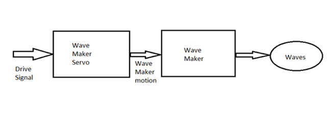
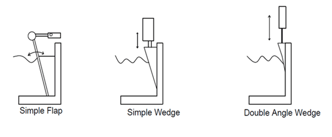
These ‘Wave Makers’ are mostly driven through electrical motors and can be expensive in construction. The basic principle of most of the wavemakers is the movement of a hydraulic ram triggered by the servo-motor which receives electric or digital signals as input. The schematic block diagram is shown below:
Another big problem that arises is the need to damp or attenuate the waves after the completion of the experiment. So for this purpose, wave absorbers are placed at the end of these flumes.
These are generally mechanical barriers, sometimes simply stones and gravels resembling banks or shores. The main experiments done in flumes are mainly seakeeping (heave, pitch, roll) ones emulating practical sea conditions.
A contrasting feature that flumes have with wave basins apart from the dimensions and purpose is that wave flumes are capable of generating only ‘unidirectional’ and ‘solitary’ waves; i.e. the models are tested in a head sea and following sea conditions.
The following figures illustrate the configurations of wavemakers which are generally observed:

In our next article of this series, the main modelling scale aspects and the proper instrumentation would be discussed. Also, a brief outline of the common experimentation types and their purpose would be given.
We will also take a brief insight into the basic principles of the Computational Fluid Dynamics (CFD) approach subsequently.
Over to you..
Do you know more about the basics of model testing of ships? Let’s know in the comments below or email us at – info@marineinsight.com
Do you have info to share with us ? Suggest a correction

About Author
Subhodeep is a Naval Architecture and Ocean Engineering graduate. Interested in the intricacies of marine structures and goal-based design aspects, he is dedicated to sharing and propagation of common technical knowledge within this sector, which, at this very moment, requires a turnabout to flourish back to its old glory.


Latest Naval Arch Articles You Would Like:
Subscribe To Our Newsletters
By subscribing, you agree to our Privacy Policy and may receive occasional deal communications; you can unsubscribe anytime.
i am a student in naval architecture and marine engineering what ever information you post here is very much important for understanding the incidents easily and simply thank you very much for your this corporation to the naval architecture field
Thank you, Mr. Shubhodeep Ghosh, for posting this info. I am interested mainly in Towing tank test and the measuring devices employed. Please share the link to the article if you have already posted.