

Types of Rudders Used For Ships
Have you ever noticed that ships, unlike most aeroplanes do not have the same kinds of rudders? The type of rudder that would suit a particular ship is a decision that needs to be based on various factors like hull form, speed, propeller design, the structural arrangement of the stern, clearance between the propeller and the stern, and also a few hydrodynamic factors that dictate the flow of water aft of the propeller.
How ship designers go about deciding the type of rudder, is actually an iterative process. In the concept ship design stage, we actually do not (or cannot afford to) decide the suitable rudder for the ship. So what designers and naval architects do is, estimate a very approximate dimension of the rudder along with the propeller. But as we enter the preliminary design of the ship, the rudder and propeller dimensions are almost fixed, giving us an almost clear idea of the type of rudder that would best fit the design problem.
However, what becomes significantly important from a designer’s point of view, is deciding on the type and location of the rudder, depending on the hull and propeller design.
Let’s try to understand this in a simple way.
The selection of the proper type of rudder is as important as the location of the rudder behind the propeller. The location of the rudder should be such that it is properly oriented within the propeller’s outflow, so as to produce the required turning moment on the ship (Before we go ahead, you might like to read How does a rudder work on a ship?). A slight change in the rudder type, dimension, and position can bring about a huge variation in the ship’s response to the rudder, as well as the turning ability of the ship. So, optimization is the key.
Related Reading:
Understanding the design of ship propeller
Understanding the design of container ships
Understanding the design of oil tankers
Types of Rudders For Ships
To broadly categorize conventional rudders, there are two types of ship rudders:
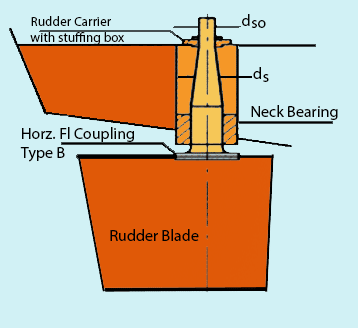
1. Spade or Balanced Rudder
A spade rudder is basically a rudder plate that is fixed to the rudder stock only at the top of the rudder. In other words, the rudder stock (or the axis of the rudder) doesn’t run down along the span of the rudder. The position of the rudder stock along the chord of the rudder (width meaning, from the forward to aft end of the rudder) actually decides whether the rudder is balanced of semi-balanced one. In balanced rudders, (which spade rudders generally are) the rudder stock is at such a position such that 40% of the rudder area is forward of the stock and the remaining is aft of it.
A genuine question that must have come up in your mind is, why is such a position chosen for the rudder stock? The answer lies in simple physics. The centre of gravity of the rudder will lie somewhere close to 40% of its chord length from its forward end. If the axis of the rudder is placed near to this location, the torque required to rotate the rudder will be much lesser than what is required to move it, had the axis been placed at the forward end of the rudder. So, the energy requirement of the steering gear equipment is reduced, therefore lowering the fuel consumption of the ship.
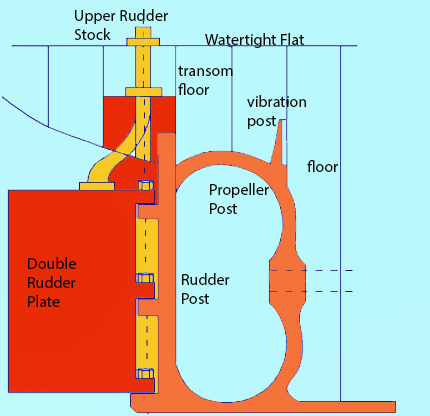
2. Unbalanced Rudders
These rudders have their stocks attached at the forward most point of their span. Unlike balanced rudders, the rudder stock runs along the chord length of the rudder. The reason is simple. In this case, the torque required to turn the rudder is way higher than what is required for a corresponding balanced rudder. So, the topmost part of the rudder has to be fixed to the spindle so as to prevent it from vertical displacement from its natural position. However, unbalanced rudders are not widely used now.
Having discussed the conventional types of rudders, let us shift into something yet more interesting. Researchers and ship operators had found significant problems with the balanced and unbalanced rudders. That is, in case there was a failure of the steering gear mechanism while turning a ship. The rudder would remain still with its angle of attack in that condition. The solution to this was found in designing an optimized Semi-Balanced Rudder.
a. Semi- Balanced Rudder:
If you have been able to visualize a balanced and unbalanced rudder by now, it should be pretty easy to visualize a semi-balanced rudder. In fact, the rudder you see on most ships are semi-balanced in the modern industry. The name semi-balanced itself implies, that the rudder is partly balanced and partly unbalanced. If you refer to the figure below, you’ll see that a portion of the chord length from the top is unbalanced, and the remaining chord length is balanced. Why? Read on.
The top part being unbalanced will help in acting as structural support to the rudder from vertical displacement. And the balanced part will render less torque in swinging the rudder. As a result, a semi-balanced rudder returns to the centreline orientation on its own if the steering gear equipment fails during a turn.
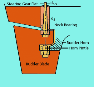
Note in the above figure the Rudder horn. Semi-balanced rudders are again of two types depending upon the depth of the horn (which affects the response and torque characteristics of the rudder). A shallow horn rudder will have a horn which extends hardly half the chord length of the rudder from the top. Whereas, a deep horn rudder will feature a horn deeply extending up to more than 50 % of its chord length from the top of the rudder.
Apart from these, designers have developed some other, rather unconventional rudder systems, which gets more interesting to look into.
Related Reading:
Understanding the design of ship’s hull
Different technologies to measure hull stresses
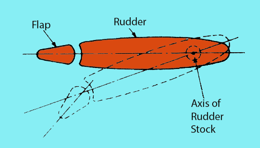
b. Flaps Rudder:
You must have watched an aeroplane’s wings closely. Did you watch those flaps coming in and out of the aft end of the wing? Why do you think they do that? Primarily to change the effective angle of attack of the entire aerofoil section of the wing. You’ll see, during a takeoff, how all the flaps are completely deployed. That actually helps in attaining the effective angle of attack so as to get the maximum lift force.
The same principle, when used in rudders, provides a similar result. Just that, in case of rudders, the flaps are not retractable and they have their significant effects when the rudder is given some angle of attack.
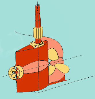
c. Pleuger Rudder:
Perhaps one of the most innovative rudder mechanisms you will ever come across. Suppose you have a ship, too large to be manoeuvre in a basin with size constraints, such that the ship cannot use its propeller during the manoeuvre. This situation often arises in case of large ships operating in space-constrained basins, or in any case of low-speed manoeuvres.
So, a Pleuger rudder (as you can see in the figure below), has a smaller auxiliary propeller housed within it (which runs by a motor). As this housing is mounted on the rudder itself, it generates a thrust (which is smaller than what is generated by the ship’s main engine propeller) in a direction that is oriented along the rudder, therefore allowing effective manoeuvre in slow speed condition.
Such a rudder can be used in normal conditions also. Just that, in normal speeds, the Pleuger is not operated. However, when the Pleuger is run, the main engine propeller must not be operated simultaneously, which will otherwise cause the Pleuger to be torn away.
Related Reading:
Different types of dry docks for ships
Voith Propulsion:
You must be wondering why a propulsion system has popped into the discussion when we are interested in rudder systems. Well, that’s something you need to thank the researchers for. Because this propulsion system is one of a kind, which acts as a rudder itself. It doesn’t need a rudder control surface to change the direction of the ship. How? Read on.
As you can see in the figure below, this propeller has a completely different orientation. To visualize it in simple terms, it consists of a number of hydrofoil blades mounted on a disc, which is in turn, mounted onto the hull. The disc rotates in a horizontal plane, about a horizontal axis, and therefore imparts a rotation into the blades.
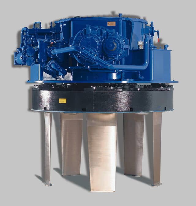
But how does a rotation in horizontal plane impart thrust to the ship? Here’s the answer. The blades themselves can be adjusted to have a varying angle of attacks during the operation of the propeller. Depending on that, the direction and magnitude of thrust are varied. Well, if we are manipulating the direction of the thrust too, then we don’t actually need a rudder. Which is actually why a Voith propeller acts as a combined propulsion and steering system for the ship.
It is of no doubt that propulsion and steering systems have been innovated and invented to a great extent when compared to many other aspects in the ship design industry which still require the eyes of modern technological applications. However, as we are transiting into an era of faster, and environmentally safer technologies, newer hull forms are being developed. This has given the industry a wider scope to develop and design newer steering systems for the future.
Related Reading:
Understanding the shipbuilding process
Understanding the design of bulk carriers
Disclaimer: The authors’ views expressed in this article do not necessarily reflect the views of Marine Insight. Data and charts, if used, in the article have been sourced from available information and have not been authenticated by any statutory authority. The author and Marine Insight do not claim it to be accurate nor accept any responsibility for the same. The views constitute only the opinions and do not constitute any guidelines or recommendation on any course of action to be followed by the reader.
The article or images cannot be reproduced, copied, shared or used in any form without the permission of the author and Marine Insight.
Do you have info to share with us ? Suggest a correction


Latest Naval Arch Articles You Would Like:

Subscribe To Our Newsletters
By subscribing, you agree to our Privacy Policy and may receive occasional deal communications; you can unsubscribe anytime.
Web Stories


If you can try and give the semi balance rudder pintles clearances which we have to keep maximum and minimum. If you can give me in detail I would be mush happy.
Thank you
Distance of rudder from the stern frame should be how much ?
by seeing how we find which type of rudder it is
can u plz explain how does the load is transmitted to rudder from steering gear?????
@Subhash: Please check this article: https://www.marineinsight.com/naval-architecture/understanding-steering-gear-ships/
It was informative. I like your materials very much. I think a few more things could be added here. You mentioned nothing about so called Rotor Rudders, nor the T-Rudders ( combination of Flap + Rotor). Also Schilling rudders, which have very specific hydrodinamic shape, could be mentioned. Combination of Twin Schilling rudders is actually astonishingly mobile.
Thank you for the value addition