

Understanding Propeller Hubs – Design, Functioning, and Maintenance
The propulsion system of a ship is one of the most important systems of any seagoing vessel. The engine room is said to be the heart of the ship, and it provides enormous thrust to move the vessel across the oceans of the world. It is built from several integral parts that work in tandem to successfully power gigantic vessels.
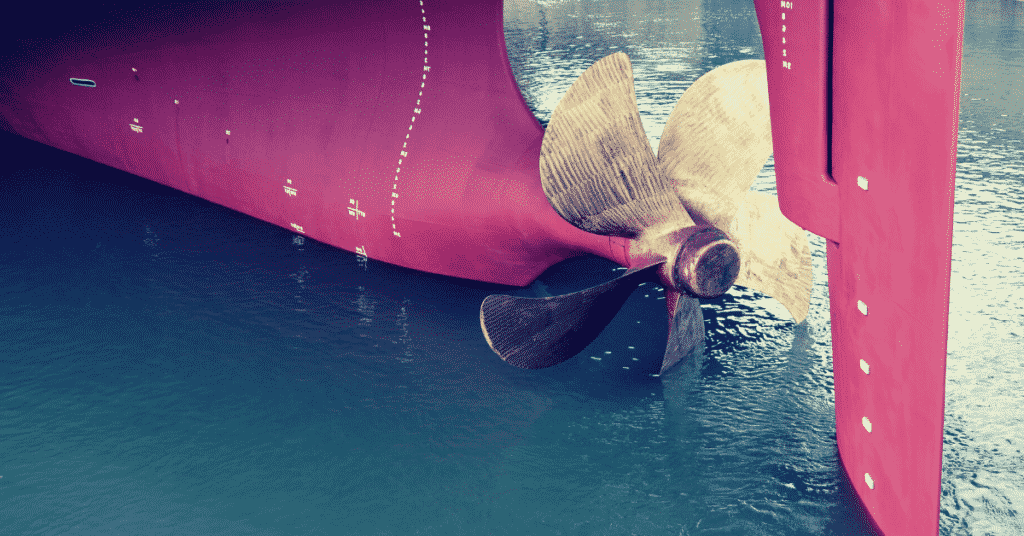
One such component is the propeller hub that plays a crucial role in providing the necessary support required to move the vessel.
In this article, we will look at the design, functioning, and maintenance of propeller hubs. We will also study how the hub controls a specific type of propeller design- the Variable Pitch Propeller (VPP).
Propulsion System and Hub Structure
Ships work on a very complex propulsion system that generates enormous amounts of thrust to power the vessel.
On average, most ocean-going ships can weight anywhere between 100,000 DWT to 500,000 DWT at a fully loaded condition, while smaller boats and yachts stay below 10,000 DWT. Thus, the propulsion system must cater to a wide variety of vessel weights and types.
Marine propulsion systems work on Newton’s Third Law which states that “Every action must have an equal and opposite reaction”.
At the stern of the ship, fluid mass is rapidly ejected from the propeller blades in a backward (astern) direction which creates a forward reaction force that propels the vessel.
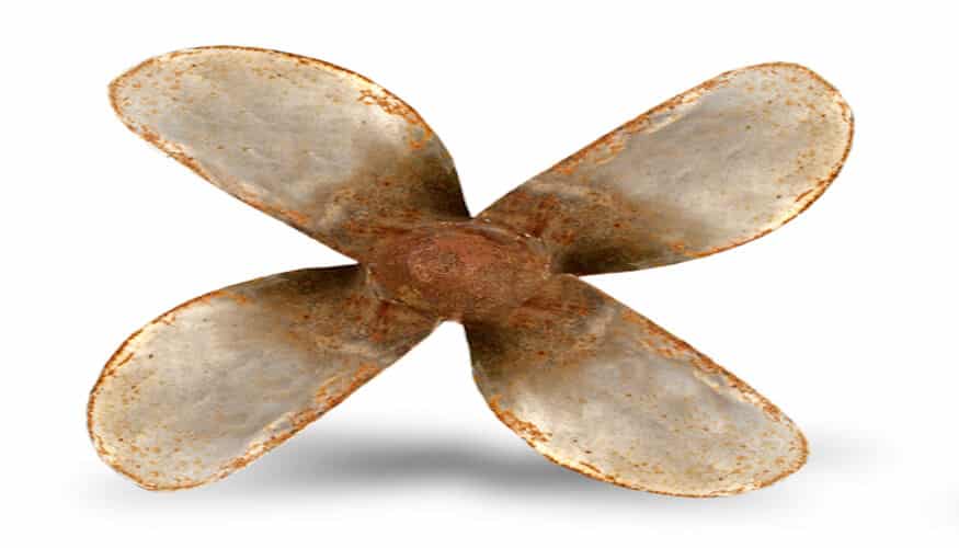
The primary thrust is delivered through two to three large propellers located at the aft of the vessel below the waterline. These propellers generally have between 3 to 6 blades per unit depending on the type and size of the vessel. A larger number of blades is preferable as it reduces the effects of a phenomenon known as cavitation.
What is Cavitation?
Briefly put, cavitation is the sudden vaporization of water around the blade edges due to a dynamic pressure difference. This pressure difference arises due to the high-speed motion of the blade’s trailing edge which energizes water particles on the blade surface.
The vaporization creates dents and speeds up wear and tear on the blades. It also rapidly drains energy away from the fluid mass being pushed behind the ship, thus slowing the vessel down even when at top speed.
In order to reduce the effects of cavitation created by high-speed propeller motion, the rpm is decreased, while the number of blades is increased. Thus, despite the lower speed of the system, the large number of blades are able to generate sufficient fluid thrust so that the ship is powered forward.
Cavitation affects the propeller hub as well and can lead to structural damages in the design. This may lead to unpredictable vessel response to manoeuvres and steering.
The motion of the propeller unit at the stern is powered using large marine diesel engines located inside the hull of the ship. Most ships use 1 to 2 marine engines for each propulsion unit. The diesel engines work on two or four stoke modes of alternating expansion and compression cycles. The piston cylinders inside the engine are forced in an oscillatory motion that powers a crankshaft attached to the engine. The crankshaft provides the driving torque that powers the vessel.
But how is the rotational motion from the crankshaft and marine propeller shafts transferred to the blades at the extreme aft? This is where the propeller hub comes into play.
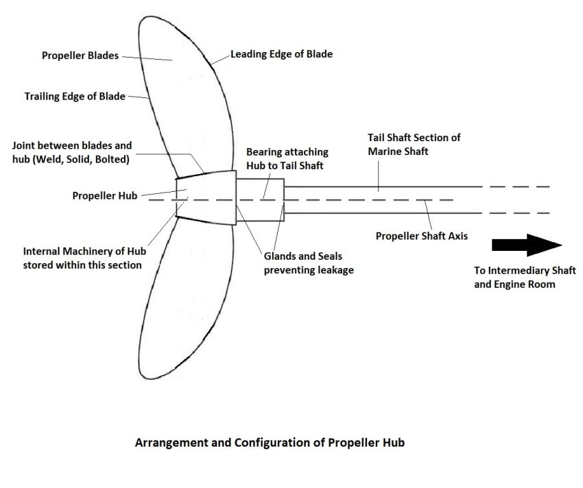
The engines transfer torque to the marine propeller shaft which carries the rotational motion to a structure known as the propeller hub. The hub rotates through its casing and further powers the propeller blades.
The hub is an integral component located on the exterior of the ship that is connected to the propeller blades. As the hub rotates, the blades are also forced through the water.
For a transfer of torque, the hub is connected to the marine shaft through the stern tube and surrounding bearings. Special provisions are made to ensure complete proofing from water entry and leakage of essential fluids such as oil and hydraulic liquids.
Design, Manufacture, and Functioning of Propeller Hub
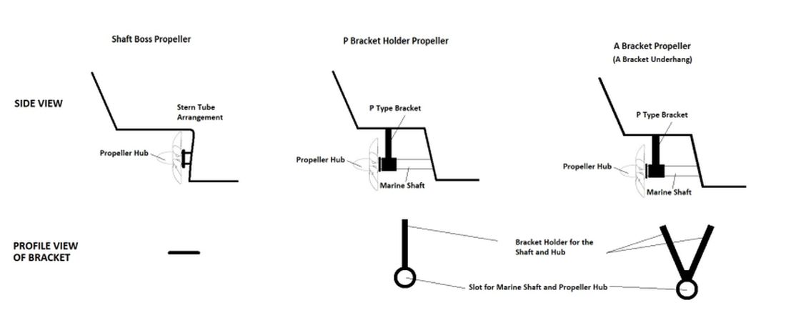
The propeller hub is required irrespective of the manner in which the propeller shaft exits the hull of the ship. There can be three main types of exits-
- Shaft bossing,
- P bracket holder, and
- A bracket holder.
Shaft bossing refers to the arrangement in which the propeller hub is placed right at the mouth of the stern tube, such that there is almost no portion of the marine shaft that is externally located.
On the other hand, the A and P bracket holders are built as overhang appendages that are located astern of the stern tube. They are more common on cruiser type sterns as compared to transom sterns. The marine shaft passes through the stern tube and then through the bracket supported by either a P or A type holder. The shaft terminates astern of the bracket at the propeller hub.
Choosing between the different arrangements depends on the vessel type and restrictions on shaft exposure. However, depending on the arrangement, the hub must be properly constructed.
In shaft bossing, the hub is partially exposed to the external fluid. Thus, it must be internally waterproofed, and special gland systems are used to prevent the leakage of any fluids across the hub.
In addition, the hub must be well lubricated so as to reduce friction within the stern tube. For P and A bracket arrangements, the entire hub is exposed to water.
Due to the extended length of the propeller shafts, vibrational and catenary forces will act on the hub. Thus, it must be suitably built to withstand large vibrational shocks. Waterproofing is required, but only to prevent fluid entry into the internal mechanism.
Depending on the hub and blade configuration, there can be two main types of propellers-
- Solid propeller, and
- Built-up propeller.
If the propeller blades are directly integrated with the hub, the design is known as a solid propeller. On the other hand, if the blades are bolted into place on the hub, the design is a built-up propeller. Each comes with its own advantages and issues depending on the type and classification of the vessel.
Solid propellers take less time to manufacture as opposed to the other variety since the blades and hub are cast in a single operation.
Integrating the blades into the hub is achieved either by casting them together or welding the blades separately. Fuse welding the blades is generally not preferred since the joints are the weakest points in the entire structure, despite receiving the largest reaction forces.
On the other hand, casting the entire propeller unit requires considerable expertise. Choosing the best option depends on the type of use and force limits that the unit may encounter. Although solid propellers comparatively take lesser time, the casting must be successful in the first operation, else it may result in delays on the project. In addition, it is very expensive due to the high level of technology and expertise required to cast a large propeller in a proper manner.
In built-up propeller units, the blades are separate from the propeller hub and have to be bolted in place. Specialized fasteners are used to secure the joint and are made waterproof to prevent the accumulation of fluid within the inside of the hub.
The benefit of using built-up propellers is that the entire assembly need not be completely disassembled, and only the required region needs to be removed. For instance, if a single blade needs to undergo maintenance, only it has to be removed.
On the other hand, the entire unit would have to be removed in the case of a solid propeller. Unlike welded solid propellers, the blades are not welded to the hub and are instead only bolted. By using adequate fasteners, this slightly increases the resistance to vibrational and other operational shocks. However, the fasteners have an increased chance of coming loose in case of shocks above the operating limits.
Another advantage of using built-up propeller hubs is that the angle of pitch of the blades can be changed to cover a wide variety of thrusts. Such units are known as Variable Pitch Propellers (VPPs) and are covered in detail in the last section. The propeller hub plays a major role in the VPP unit since it houses the essential machinery.
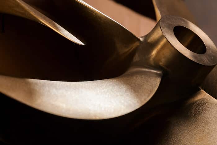
The preferred materials for casting propeller hubs are copper and bronze alloys for large ships. Smaller vessels mays use aluminium, bronze, and nickel alloys. Bronze and copper are chosen for their high tolerance to rusting and corrosion, as well as strength and durability.
Aluminium is chosen since it is extremely light while also possessing a high structural strength. In fact, aluminium has one of the highest strength-to-weight ratios amongst metals, a property that is highly preferred when it comes to commercial manufacturing of heavy machinery.
The glands and other sealing materials that prevent leakage are generally part of the stern tube but can be integrated into the propeller hub to increase efficiency. The sealants can vary depending on the ship configuration and structure.
Sealants such as packing boxes, lip seals etc. are used at the junction where the hub is connected to the marine propeller shaft.
Maintenance Operations For Propeller Hubs
The hub is an important rotational component that needs to be regularly serviced and maintained so that the vessel functions smoothly.
It is acted upon by several forces including vibrational forces, submerged water pressure, centrifugal forces etc. To access the propeller hub, the vessel needs to be taken to a dry dock such the keel portion is exposed. Then, heavy-duty cranes are used to hold the propeller unit in place while it is disconnected and removed from the propeller shaft.
In the case of solid propellers, special lifts are then attached to the hub and gradually shift the entire unit astern of the vessel. On the other hand, for built-up propellers, if the repair is only for a single propeller blade, the hub and remaining blades are left as such while a heavy-duty crane supports the affected blade. Once the bolts are disconnected, the blade is moved elsewhere. However, if the entire unit needs to be removed, the procedure is similar to how the solid propeller unit is removed.
Common repair operations required for the propeller hub in specific include regrinding and smoothing the surface of the hub so that it achieves the intended structure. Additionally, in case of any major defects, the area is once again recast or filled in with some other alloy.
Checks are also carried out on the welds and their integrity. Depending on the type of maintenance and extent of damage, the repair period might take anywhere from a few hours to two weeks. Checks on the internal machinery in the case of VPP units and internal sealing glands of the hub are performed in addition to working on the exterior structure of the hub.
Hub Control on Variable Pitch Propellers (VPP)
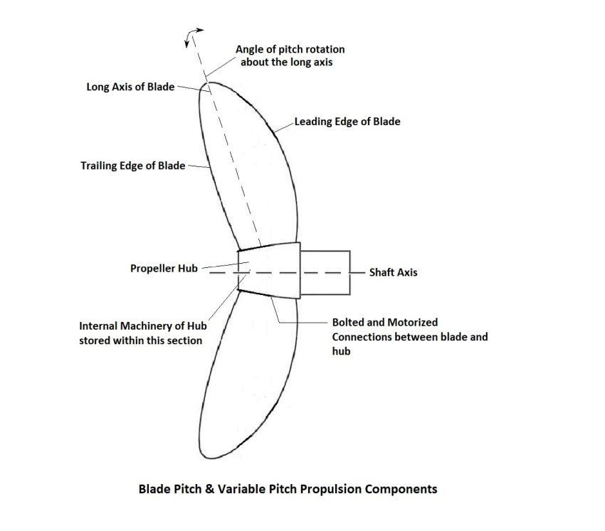
Variable Pitch Propeller (VPP) is a design that involves being able to control the angle of pitch of the propeller blades. As the blades are housed on the propeller hub, it plays an important role in manipulating the angle of pitch. The VPP is also known as a Controllable Pitch Propeller (CPP).
Pitch refers to the angle change that takes place when a propeller blade rotates about its long axis. In the case of ship propellers, the long axis extends radially outwards from the centre of the hub along the longest section of the blade.
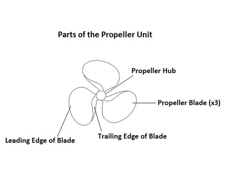
The shape of the blade is such that there are two distinct edges- the leading edge that meets incoming fluid particles, and the trailing edge that redirects the outgoing fluid mass for increased thrust and acceleration.
By rotating the blade, the angle at which fluid exits the propeller is altered which further alters the speed and control of the vessel.
For ships, VPP machinery is housed within the propeller hub. It is a highly complex technology that needs to be extremely accurate during operations. The machinery includes motors and sensors to report information to the bridge.
The blades are in the form of a built-up propeller unit but are mounted on specialized bases built on the hub. Along with fasteners, there are precise motors present within the hub that gradually rotate the blade about its long axis to achieve pitch change.
The pipeline in using the VPP is as follows:
1. Captain orders a change in pitch of the propellers and information is relayed to the relevant section of the ship.
2. The sensors on the hub are checked to ensure that the current settings are well below the permissible limits and to ensure no flooding of the internal hub space has taken place.
3. If all is in order, motors within the hub are powered to gradually rotate the base on which the blades are attached to the hub. These motors are incredibly sensitive and can change the pitch by 0.5⁰ on some ships.
4. After the required pitch change, sensors once again relay essential information on the status of the hub and internal machinery.
Pitch changes may also be automatically driven by an autonomous system that aids in navigation, steering and other operations.
The advantage of using VPP designs is that the efficiency of the engine is drastically improved. The operating RPMs can be optimized to suit the need of the vessel while also allowing for better acceleration and deceleration.
In addition, for vessels in which negative pitch can be achieved by rotating the blade in the opposite direction, the vessel can even move astern (in reverse) without needing specialized engines. Thus, it has several advantages which make it an attractive choice for large ships. However, it can be very expensive due to the advanced technology and skill needed to successfully manufacture the propeller hubs.
The hub is the most important component of the VPP design since it houses the essential machinery without which the ship’s propellers cannot function. In order to ensure that the system works without any issues, maintenance work must be carried out. However, this can force the vessel to be grounded frequently, since the only way to service the propeller hub is by accessing the keel portion of the ship in a dry dock.
Related Reading:
- Different Ways To Reduce Ship Propeller Vibrations And Increase Its Efficiency
- 10 Factors Considered For Efficient Ship Propeller Design
- Marine Propeller Shaft – Design And Construction
- 10 Precautions to Take Before Operating Controllable Pitch Propeller (CPP) on Ships
- Understanding Design Of Ship Propeller
Do you have info to share with us ? Suggest a correction

About Author
Ajay Menon is a graduate of the Indian Institute of Technology, Kharagpur, with an integrated major in Ocean Engineering and Naval Architecture. Besides writing, he balances chess and works out tunes on his keyboard during his free time.


Latest Naval Arch Articles You Would Like:


Subscribe To Our Newsletters
By subscribing, you agree to our Privacy Policy and may receive occasional deal communications; you can unsubscribe anytime.