

Different Ways To Reduce Ship Propeller Vibrations And Increase Its Efficiency
As a ship designer, you tend to seek ‘that’ optimal design, a machine/part which gives both high output and efficiency. Some of the finest machines ever designed are sometimes the ‘silent’ ones (I do not mean it is a rule). Like any other vehicle, ships too need an efficient and reliable propulsion machinery (and they have surely advanced a lot from the Paddle Wheel days).
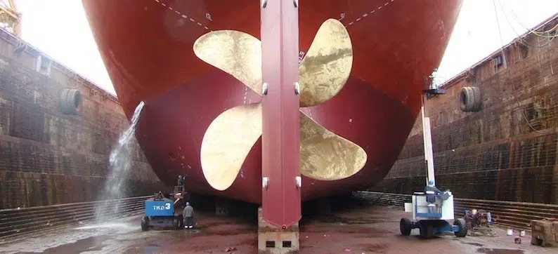
The propulsion system in today’s ships do not vary much barring the High Speed Crafts and Hydrofoils. The propellers commonly used today are called the ‘screw propellers’ – Yes, the screw which is pretty much among the greatest inventions of mankind. The screw propeller enabled the ships to move at higher speeds and with time, they have seen changes in shapes and have also become more durable.
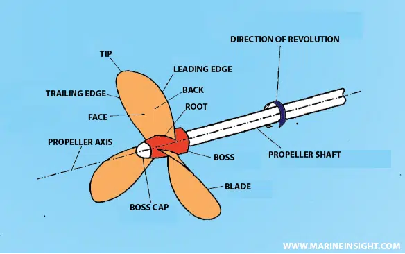
Let us have a look at the different parts of the screw propeller:
Now, like any other machine, in practical situations, the propeller has losses and these pull down the efficiency from a cent per cent output/input ratio. Among such losses, one that is quite significant is the vibration and noise. Let us see how this can be reduced:
The Geometry of it:
How about some Geometry? The path traced out by the propeller in one revolution, it resembles what is called a helix in three dimensions. Certain properties like the pitch of the propeller, the pitch angle may be found from it. But, we would not go into all that things which directly influence the noise and vibration characteristics are given.
When the section of the propeller is skewed to a certain extent (large skew is undesirable as it increases the natural frequency of vibration of the propeller) there is reduction in the amplitude of unsteady forces minimising vibration. Using more blades in certain propellers and also increasing the blade area has been seen to have a positive effect against vibration.
Suitable distribution of propeller pitch is also an important factor. As if there are abrupt changes in pitch, the pressure changes somewhat resembling pulses might affect the blade, causing it to vibrate.
Sometimes the tip of the propeller is confined within one plane using contraction of the blade tip. These kind of propellers are consequently named Tip-Vortex Free (TVF) or CLT (Contracted Loaded Tip) where the trailing edge vortices of the blade are minimised. This is because using a single plane causes the vortices at the tip to reduce in number as a result of absence of a curvature at the outgoing edge.
Think of the blade as a cantilever beam which is subjected to loading (in this case, the reaction to propelling a ship!). It is therefore desirable to have more section modulus, which can be achieved if more mass/fibre is distributed towards the root of the blade as opposed to the tip, as more distribution of mass away from the neutral axis (in this case below it) is required.
Attention has to be paid to the finishing of the propeller blades, which if not properly painted and polished, will cause cavitation to occur, and in a cyclical manner over time, will cause fatigue.
Time to ‘Wake’ up:
It is not always the propeller rotation or the varying pressure distribution around the propeller which is responsible for the loss. Sometimes the wake pattern is also responsible for the vibration levels in a propeller being high. The wake is usually a region of turbulent fluid flow around a moving body in an incompressible fluid (seawater for that sake, qualifies as one). Now, turbulence is never desirable around your ship’s propeller among all other regions of the submerged portion of your ship. Some methods exist today to reduce the impact from wake, the use of ducts like the Schneekluth duct, or the Mewis duct are among your options. These ducts, generally fitted on the hull or just before the propeller, bring in a more uniform wake flow into your ship’s propeller. Another method, simpler and easier to fit this time, is the use of a nozzle, called the Simplified Compensative Nozzle, this reduces oscillations in the inflow, and reduces the noise levels.
Confinement is the way:
Already having spoken about nozzles, who can forget about the Kort Nozzles which set about the shrouded propeller revolution? Here, a fixed nozzle is used around the propeller.
This is advantageous in cases when there is a requirement for a propeller of limited diameter. These are in use for low speed applications and should not be run at high speeds as this will cause cavitation.
The nozzles in mention are of the accelerating or the decelerating type, depending on velocity of inflow. The decelerating ducts are used if your vessel is exposed to cavitation as the resulting high pressure would inhibit the formation of cavities. Confinement is often done in warships and submarines.
Cavitation: Use it or kill it
Cavitation is the formation of the vapour bubbles on the suction side of the propeller where cavity forms as the pressure from water around it falls below the vapour pressure of water. These ‘bubbles’ are carried to the metal surface, eventually imploding on it and causing wear to the propeller blade and such a phenomenon occurring in a cyclic manner causes fatigue and eventually failure.
Sometimes cavitation comes handy in reducing friction, and this is when the phenomenon of super-cavitation is used in propellers specially designed for the purpose. They are called super-cavitating propellers. These propellers are wedge shaped when a section is considered, and the cavity can accommodate the whole suction side (back) of the propeller and hence minimises friction. These are in extensively used in high speed vessels and warships.
Other Methods
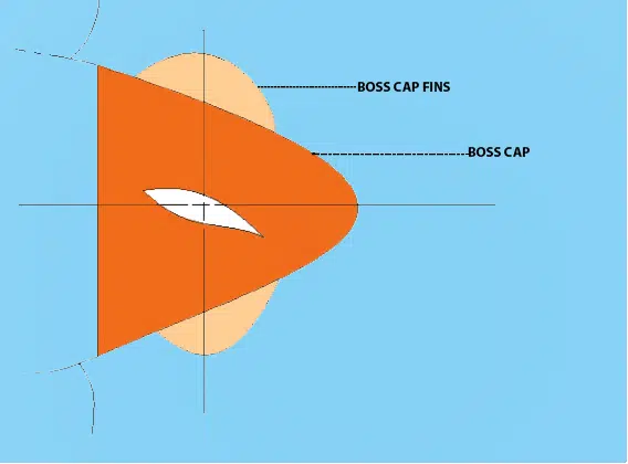
Sometimes we modify the propeller at the cap, this involves using boss cap fins which absorb the energy from circulation and reduce hub vortices, this being linked with cavitation like any other situation, reduces vibration and also the noise generated from the collapse of the bubbles, this time on the rudder surface!
Among other unconventional propulsion devices, a ring propeller is sometimes used where the ring is attached to the tip of the propeller blades; this has a similar effect like spreading the vortices of the trailing edge at the tip. Yes, lesser turbulence and tip vortex cavitation, again less noise from the ‘bubbles’ imploding on the metal surface.
Some other propulsion systems which claim to reduce vibration and noise are podded propulsion systems, fore-propellers, vane-wheel propulsion, Voith-Schneider propulsion and the like.
And so…
Finally, broadly speaking, you can play with three things while designing a low-noise propeller. You can change the downstream flow into the propeller by using ducts. Second, you can modify the geometry of the propeller. Third, simply use nozzles or ducts around and not away from the blades of the propeller. You can also use a sound absorber inside the duct. Cavitation is a problem to be dealt with seriously and of course, separately.
Unconventional propulsion devices for the most part, require rigorous field testing to prove their practical applicability and economic feasibility in comparison to conventional propulsion.
Here, some of the basic science behind certain technologies in use today were discussed, which I hope will give you a clear idea as to how vibration in various propulsion systems may be supressed.
Can you suggest more ideas which can be added to the list?
Let us know in the comments below.
Do you have info to share with us ? Suggest a correction


Latest Naval Arch Articles You Would Like:

Subscribe To Our Newsletters
By subscribing, you agree to our Privacy Policy and may receive occasional deal communications; you can unsubscribe anytime.
Y nic like the work
is high free natural frequency is good for the propeller?
i have designed propeller and i have done modal analysis by changing materials.
for MAB propeller got higher free natural frequencies (no damping and no external loading conditions) than the MNB propeller..
now my doubt is which material is best?