

What are Stern Tube Lip Seals?
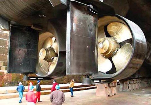
Stern tube lip seals are rotating lip seals that are used in the ship’s propulsion system. A Lip seal is a sealing arrangement used at the stern tube of a ship, preventing lubricant spillage to the environment while simultaneously preventing the incoming seawater to the stern tube. Modern ships have lip seals installed in oil-lubricated stern tube sealing systems. The lip seal forms a part of stern tube bearing and sealing arrangement and is the most commonly used sealing arrangement on ships today.
Composition
The lip seals are made up of enormous elastomers like nitrile rubber having elastic properties for gripping the rubbing surface in order to have an effective sealing. If the temperature of the seal material exceeds 110°C, the rubber will lose its elasticity property. Stern tube seals are often composed of fluoroelastomer compounds nitrile rubber, mostly of Viton brand. The excessive fluorine content permits lofty running temperatures while giving rare inertness against the mineral oils used in the stern tube Fluoroelastomers are a mixture of several monomers tailored for a particular application, and they are generally cured by bisphenol. Some other seal materials are-Aflas, Carboxylated Nitrile, Fluorinated Ethylene- Propylene, Fluorosilicone, Hydrogenated Nitrile, Polyacrylate, etc.
Lip Seal Arrangements
A lip seal arrangement comprises various nitrile elastic rings of unique cross-segment sandwiched between bronze rings. Every individual elastic lip seal is held in touch with a sustainable sleeve fitted to the shaft by its versatility and a garter spring. By cutting and then vulcanizing the extremities in situ, the rings are restored.
The simplex stern tube has a forward seal with two rings and an after sealing with three rings. The lip seals are tightly pressed against the chrome liner with the help of a garter spring, and with the rotation of the propeller, the chrome liner also rotates. The seals are developed from fundamental gatherings, specifically the flange, intermediate, cover rings, seal rings, and liner. The garter spring that holds the sealing ring against the shaft in the case of both front sealing rings is placed aft of the ring anchoring bulb. There are two outboard garter springs positioned behind the ring anchoring bulbs in the after seal and one inboard garter spring located behind the ring anchoring bulb.
There are different positions where the lip seal is placed. The outer seals dissipate the heat to outboard sea water, and the inward seals dissipate heat to the oil by convection. The oil is circulated with the help of a pump from a small header tank.
The outboard gland’s middle seal keeps the water out, and the aft seal protects the middle one from dirt and debris. The lip seals create grooving over the chrome liner due to friction which can be overcome by using ceramic filler for the grooves or by using a distance piece with some allowance to compensate for shaft and stern tube expansion.
Various Working Conditions of Lip Seals
Lip seals usually work under stress in the radial and axial directions while broadened in the circumferential direction. The final radial load resolves the minimum load-bearing magnitude. The narrow film of lubricant running between the liner and the seal needs to work within the wear-less full film lubrication system.
The fixed proximity pressure profile, and thus the total contact force, depends on the five aspects given below:
- Seal geometry
- Seal material properties
- Garter spring
- Pressure difference
- Temperature
The seal-shaft contact force is a radially uniformly distributed load along a circumference of several hundreds of centimetres; hence, it is not straightforward to measure. A specific method is repeatedly reported in the literature: the split-shaft setup.
Such a test rig consists of two semi-cylindrical jaws arrangements. One of the jaws is fixed to the bench table while the other semi-circular jaw seats on leaf springs, and it is able to slide along a rail. When the two jaws are set apart at a specific distance, they form an almost-complete cylinder representing the shaft. When the seal is mounted on the jaws, a certain load result pushes the jaws together. This unidirectional load is measured and is related to the distributed radial load between the seal and the shaft.
The split-shaft setup can be placed in a temperature-controlled chamber so that both the impact of the thermal expansion of the components and the softening or hardening of the elastomer are measured. Lee et al. presented an alternative method to measure the contact force based on the use of an inflatable mandrel. That approach has the advantage of allowing the shaft’s diameter to vary. A non-destructive method was presented by Tasora et al., in which the seal could be directly characterized by measuring its response to the misalignment of the shaft.
The contact area between the seal and the shaft is often measured by mounting the seal on a hollow shaft made of transparent material. Under ambient conditions, the contact pressure profile spans only along with a few tenths of millimetres, thus complicating the measurement of local pressures. Lee et al. used a pressure-sensitive foil to determine the pressure profile at the contact. One indirect way to reveal the contact distribution involves measuring the displacement of the seal tip in the circumferential direction after a slight rotation of the shaft.
Although inaccurate due to the unknown friction coefficient, a non-uniform displacement that agrees with the expected parabolic pressure profile has often been reported. Finite element (FE) models are utilized to foresee the contact pressure profile of seals. It is often assumed that the pressure profile does not vary along the circumferential direction, so the seals are modelled assuming axisymmetry. A non-uniform pressure, non-uniform temperature distribution, and shaft-seal misalignment are therefore disregarded. The elastomer is often modelled by linear elastic or hyperelastic constitutive models such as the Neo-Hookean or the Mooney-Rivlin. The Garter spring is usually modelled as a distributed radial load, as an independent body with a fitted stiffness.
Advancements
- Some new models have two void spaces in each gland seal, which are circulated by oil being changed several times by a circulation pump. This oil pressure is slightly less than that of seawater pressure to avoid oil pollution of the sea. It also removes the problem of high-temperature failure of seals.
- The modern stern tube lip seals are provided with fluorinated rubber sealing rings, which provide advancement in lucidity and solidity over the older type of seal.
- An oil-lubricated strengthened plastic stern tube bearing material has been introduced as a substitute for white metal. This has given exceptional results under strenuous service conditions.
Wear problems with Stern Tube Lip Seals
- The chrome liners act as a rubbing surface for the rubber lip seals but grooving from frictional wear has been a problem.
- The difficulty has been overcome by using a ceramic filler for the groove or, alternatively, a distance piece to partially displace the seal and ring assembly.
- Allowance must be made for the relative movement of the shaft and stern tube to differential expansion. New seals are fitted by cutting and vulcanizing in position.
- The wear rate becomes virtually zero if there is leakage-free full film lubrication.
- Rubber plugs are made at the seal chamber to minimize leakage of oil as well as ingress of seawater.
You may also like to read-Propeller, Types of Propellers and Construction of Propellers
References:
Marine Aux Machinery by H.D.McGeorge
Image Credits:
simplexturbulo
Do you have info to share with us ? Suggest a correction
Latest Marine Technology Articles You Would Like:
- 10 Harmful Effects Of Impure Air On Ship’s Machinery

- 10 Important Things to Check While Starting Fuel Oil Purifier on Ships
- 10 Noteworthy LNG-Powered Vessels
- 10 Points for Efficient Turbocharger Operation On Ships
- 10 Practical Tips to Handle Engine Room Pumps
- 10 Precautions to Take Before Operating Controllable Pitch Propeller (CPP) on Ships


Subscribe To Our Newsletters
By subscribing, you agree to our Privacy Policy and may receive occasional deal communications; you can unsubscribe anytime.