Ship Stability – What Makes a Ship Unstable?
A thorough knowledge on curves of intact stability can help us know and analyse real cases of instability caused in surface ships. For each case of instability, a ship designer must first know the effect it would cause on the ship. Once the effect is known, the cause of the vessel instability is investigated. In practice, the main tools used for analysing the causes of all cases of instability of a ship are Loading Condition and Stability Curves.
A certain level of intuition based on experience with surface ship stability also plays a major part in pointing out the cause for each case, which makes stability an even more interesting area of research in the field of naval architecture.
We will first discuss some major cases of instability in surface ships. Once the effect of each has been studied, we will then see what measures are taken in design and operational stages to prevent the same. We will also relate each of these to real cases that have occurred in the past.
Free Surface Effect Of Ships:
When any tank or a compartment is partially filled, the motion of the liquid (due to the ship’s rolling and pitching motions) would reduce the stability of the ship. Why? Because, when the ship is inclined, the liquid in the tank shifts to the lower side of the tank, as shown in the following figure.
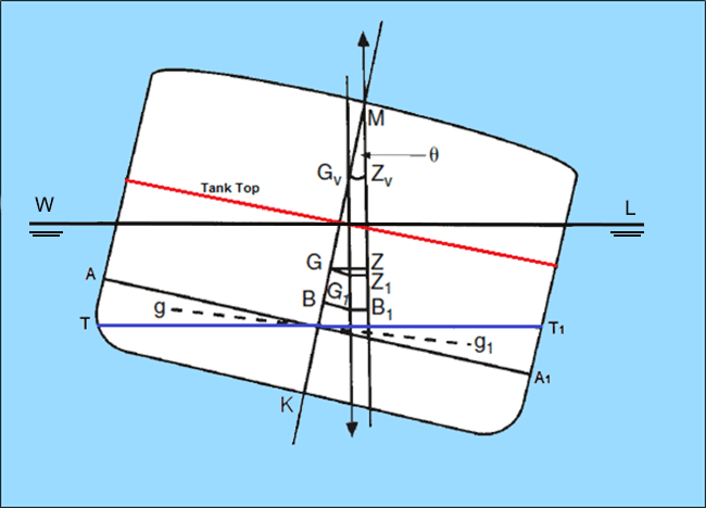
In the above figure, the ship tank extends from the bottom to the tank top (shown in red), and is only partially filled. When the ship is in upright position, the free surface of liquid in the tank is shown as AA1. When the ship inclines to a certain angle of heel (say ‘theta’ Ɵ) the free surface of the liquid now changes to TT1. Also, the center of buoyancy shifts from ‘B’ to ‘B1’.
What happens as a result of this? Do note that when the liquid in the tank is transferred to the lower side, the volume of the liquid within the wedge between points ‘A’ and ‘T’ has now shifted to the lower side between the points A1 and T1. So basically, the center of gravity of that volume of liquid has shifted from ‘g’ to ‘g1’.
As a result of the weight shift within the ship, the center of gravity of the ship now shifts from ‘G’ to ‘G1’. The effect of this shift of liquid is such that the resultant weight of the entire system acts through a virtual point which is much higher than the actual center of gravity of the ship. This virtual center of gravity ‘GV’ is obtained by extending a vertical line from the new center of gravity ‘G1’ to the centerline of the ship. So the resultant KG increases, therefore reducing the metacentric height of the ship.
The new metacentric height with free surface effect is now ‘GVM’, and the new righting lever is ‘GVZV’, both of which are significantly less than the original values (without free surface effect). It is this reduction in the metacentric height, or rise in the CG of the ship due to free surface effect, that reduces the stability of the ship or may even render it unstable.
This reduction in metacentric height due to free surface effect can be calculated by the following expression:
In the above expression,
?L = Density of the liquid in the tank.
?S = Density of seawater.
IL = Area moment of the free surface about the tank’s longitudinal centre line.
∇S = Mass displacement of the ship in sea water.
There are some very important conclusions that can be drawn from the above expression, and these are used to develop design methods to combat free surface effect on ships. They can be enlisted as:
- The effect of free surface is independent of the position of the tank. That is, a tank may be at any height within the ship, or at any longitudinal position, and the development of any free surface in it would affect the ship in the same way irrespective of its location.
- Reduction of metacentric height due to free surface effect is more for denser liquids.
- The shape of the tank plays a major role in the evaluation of free surface effect. That is because, reduction in the stability of the ship is directly proportional to the area moment of the free surface about the tank’s longitudinal centerline. What does this imply? The lesser transverse surface area of the free surface, lesser its area moment of inertia about the tank’s longitudinal centerline, lesser the reduction in GM due to free surface effect.
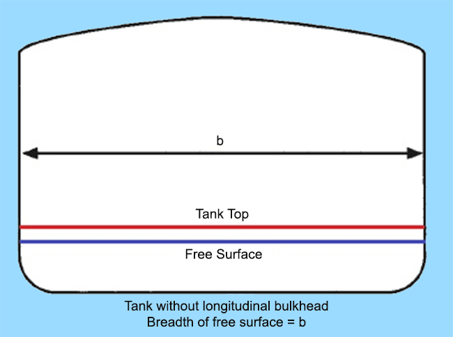
In order to attain this, a design priority during the design of tanks is to reduce the longitudinal moment of the free surface by providing longitudinal bulkheads in tanks having large surface area, as shown in the figure below.
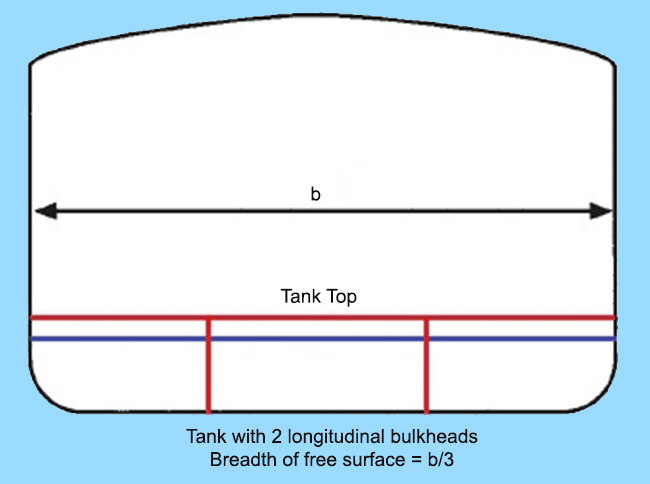
In the first case, a tank with breadth same as the beam of the ship (b) would have produced significantly high reduction in GM due to a free surface. If the same tank is compartmentalised into three equal parts by providing two longitudinal bulkheads, the free surface would reduce by a factor of cube of the breadth of the tank (b). If you study the tank plan of any ship, you would notice that large fuel and fresh water tanks are divided into Port, Center, and Starboard compartments for this reason.
Free Surface Effect For Two Liquids:
There are cases where one tank contains two immiscible liquids. In fuel compensation tanks, the volume of fuel oil used is replaced by sea water. In gasoline tanks, seawater is introduced into the tank in order to prevent leaving any spaces for inflammable vapours. Gasoline being lighter than sea water, always forms the top layer, and is extracted from the top of the tank.
The interesting question here is, these tanks are always full. How is free surface effect related to these cases, then? Note the following figure.
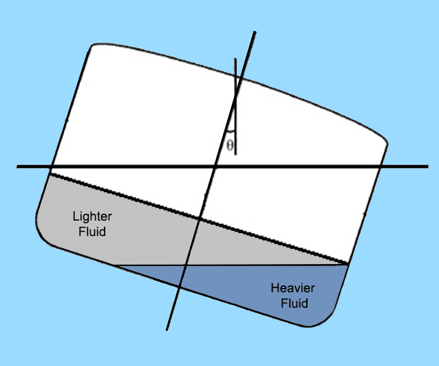
What happens is, the interface of the two liquids act as a free surface. So when the ship inclines, the interface will remain parallel to the waterline. In order for this to happen, the certain volume of the heavier liquid needs to shift to the lower side of the ship, replacing certain volume that was occupied by the lighter liquid. The replaced volume of the lighter liquid in turn, shifts to the upper side. The resultant effect is a shift of CG due to the motion of fluids, which creates a free surface effect.
Effect of Shifting of Dry Bulk Cargo:
In ships carrying dry cargo in bulk like grains, ore, coal, etc. even though the surface of the cargo is flattened after loading, rolling motion during voyage is likely to redistribute the cargo within the hold, causing it to shift to one side. This will result in a list towards one side. Now, a ship which has listed due to shift in cargo is vulnerable to capsizing in case rolling increases to larger angles. In fact, bulk carriers have been known to capsize due to shift of cargo.
In order to prevent such cases, designers are supposed to make sure that their design complies with the IMO Code of Safe Practices for Solid Bulk Cargoes (IMO, 1980). The Code provides a list of technical specifications for each type of bulk cargo and their respective angles of repose. What we will focus on, in this section, is not the details of the Code, since it is a specific document and is easily obtainable. What’s important here, is to see how shift in cargo affects a ship’s stability.
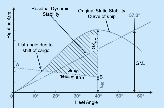
The above figure is the representation of the ship’s stability during shift of dry cargo. The dotted curve ‘AB’ plots the heeling arm or lever caused due to grain shift. To generate this plot, analysis is carried out for various loading conditions, and accordingly a range of grain heeling plots are obtained. Each plot should be treated as a separate case for analysing the stability of the ship at each load case.
Now, imagine a ship in which grain has shifted to one side. The ship would list upto an angle at which the grain heeling moment would cancel out the righting moment. Graphically, this point is achieved where the curves of grain heeling arm and static stability curve of the ship intersect.
In case of grain shift, the resultant maximum righting arm of the ship also reduces. How? Let’s say, maximum GZ for the given case occurs at a heel angle of 40 degrees. Due to existence of a grain heeling arm at 40 degrees (ƛ40) the resultant maximum GZ would be (GZMAX – ƛ40).
The dynamic stability of a ship is the area enclosed within its static stability curve. It gives us the magnitude of external heeling energy that the ship can absorb before capsizing. The area accountable to dynamic stability reduces due to the presence of a grain heeling arm. In other words, in case of absence of a cargo shift, the area contributing to dynamic stability would be the area between the static stability curve and the horizontal axis. Whereas, the area between the heeling arm curve and the horizontal axis is reduced from the original area when cargo shifting occurs (shown as shaded portion in the above figure). This means, the ship can now absorb less external energy (wind, waves, centrifugal force due to high speed turns) before capsizing.
Therefore, the following design constraints are taken care of in order to prevent loss of stability due to shift of dry cargo:
- The value of initial transverse metacentric height (GMT) assuming free surface effect to be present. It must not be less than 0.3 meter.
- The value of initial transverse metacentric height (GMT): It should not be less than 0.3 meter if we consider that the free surface effect is present.
- Angle of list due to shift of dry cargo. As per the code, this value should not exceed 12 degrees in any sea state.
- Angle of list due to shift of dry cargo: As per the code, this value should not exceed 12 degrees in any sea state.
- The value of grain heeling arm at 40 degrees heel. This constraint is laid down, assuming the fact that most ships attain maximum GM at 40 degrees heel angle.
- The value of grain heeling arm at 40 degrees heel: This constraint has been set assuming the fact that most ships attain maximum GM at 40 degrees heel angle.
The slope of top-side tanks and size of the cargo holds, hence, play a major role in preventing shift of dry cargo within a dry bulk carrier.
There are a range of other reasons for rise in the center of gravity of a ship, or in other words, reduction in its stability. We will list and discuss some of them below:
- Collapse of a longitudinal bulkhead or a tank bulkhead may lead to rise in the CG as it would increase the moment of inertia of the free surface.
- Stability of a ship is significantly reduced due to build-up of ice on it superstructure. It not only causes unwanted angles of list, but also unwanted trim conditions. Often, list due to icing of superstructures is a result of asymmetrical accumulation of ice, which causes the center of gravity of the ship to shift. The resultant value of righting arm would be significantly less for all angles of heel, therefore causing a reduction in:
- Maximum GZ
- Initial transverse metacentric height.
- Dynamic stability.
- Range of stability.
Icing also increases the windage area of the ship, causing the wind heeling moment to rise, and the dynamic stability to further decrease in case there are beam winds.
- Entry of water into the ship through badly maintained hatches could result in flooding between the tween decks. There have been cases where open doors on weather decks have allowed water ingress causing significant rise in CG due to flooding of top level decks.
- Timber deck cargo can often be accumulated on one side of the ship due to heavy rolling in bad weather conditions. The shift in cargo would result in a list, and there have been cases where the timber cargo ships have been forced to voluntarily lose a part of their cargo to the sea in order to correct dangerous angles of list.
A very interesting question arises here. If, during an unloading operation, a timber deck cargo ship has a list to the port side due to accumulation of timber on the port side, which side should be unloaded first in order to correct the list?
Someone with only a basic intuition would obviously say that since the cargo is port side is the lower side (and there is excess cargo in the port side), the ship must release cargo from the port side itself. But this would capsize the ship. Why? Because while it may appear that removal of excess cargo from the lower side would upright the ship, what actually happens is, weight is being removed from the lower side. It means, the center of gravity shifts upwards, resulting in a decrease in metacentric height, and hence, the margin of stability decreases drastically.
Concept of Heel, List, and Loll:
We have used all the three terms a number of times in this and the previous articles of this series. While all the three terms would mean that a ship is inclined to a certain angle, they do not mean the same. As in, they are terms used to understand the ‘cause’ behind the inclined condition of the ship.
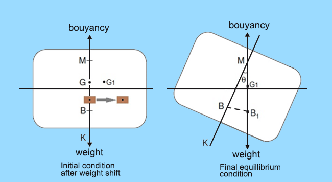
List : A ship is said to be in a condition of list when the upsetting moments are caused by internal shift of weight that can be caused due to the following actions:
- Shift of cargo within the ship.
- Free surface effects.
- Crowding of passengers on one side of the ship.
- Asymmetrical icing on the superstructure.
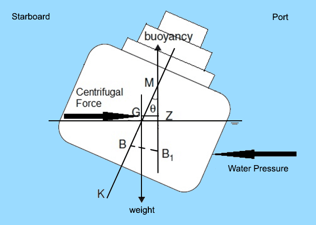
Heel: A vessel is said to be heeling when the upsetting moments are caused by external agents, for example:
- Beam winds.
- Heel due to a high speed turn.
- Heel due to a missile shot in transverse direction (in warships).
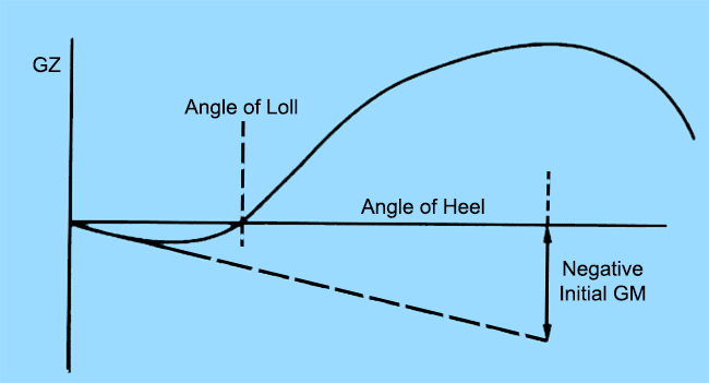
Loll: The condition of loll is completely different from the above two. A ship is said to have an angle of loll when it is investigated that the ship has a negative initial stability, or a negative initial metacentric height, as shown in the curve below.
A negative initial GM may occur due to the following reasons:
- Free surface effects.
- Flooded compartments.
- Top heaviness – or excessive loading on upper decks.
- Accumulation of green waters on the weather deck due to clogged scuppers.
The analogies discussed above leave us with two very important inferences:
A ship with a heel or a list is not necessarily unstable, as heel or list does not imply that a ship has a negative value of GM. However, the case of instability cannot be ruled out unless the GM values are checked. But a ship with a loll is definitely an unstable ship because it has a negative GM in upright condition.
The importance of understanding stability of ships lies in appreciating that, without all the concepts that we have been discussing and the approaches we have adopted in understanding stability, it is impossible to understand the inferences. It is based on inferences such as these, that designers and experienced ship crew develop a sense of intuition towards analyzing cases of ship’s stability.
Disclaimer: The authors’ views expressed in this article do not necessarily reflect the views of Marine Insight. Data and charts, if used, in the article have been sourced from available information and have not been authenticated by any statutory authority. The author and Marine Insight do not claim it to be accurate nor accept any responsibility for the same. The views constitute only the opinions and do not constitute any guidelines or recommendation on any course of action to be followed by the reader.
The article or images cannot be reproduced, copied, shared or used in any form without the permission of the author and Marine Insight.
Do you have info to share with us ? Suggest a correction
Latest Naval Arch Articles You Would Like:
Subscribe To Our Newsletters
By subscribing, you agree to our Privacy Policy and may receive occasional deal communications; you can unsubscribe anytime.



I really love the content, it is both informative and educative
I really love the content, it is both informative and educative
Interesting Article