

Submarine Design: Unique Tanks On a Submarine
This is the third part of the series of submarine design. Please read the first two here – Introduction to submarine design and Understanding submarine design.
Though some of the tanks used in a submarine are similar to that used on surface ships, most of them are different and unique to the nature of operation of a submarine, which makes it an important aspect to be studied in detail.
For a quick glimpse, did you know why a submarine uses a system of four tanks just in the process of firing one torpedo?
We will first look into the tank plan of a diesel electric submarine and as and when we familiarise ourselves with their terminologies, we will study their functions, the reason behind their location, and other design aspects related to them.
Tank Plan of a Submarine:
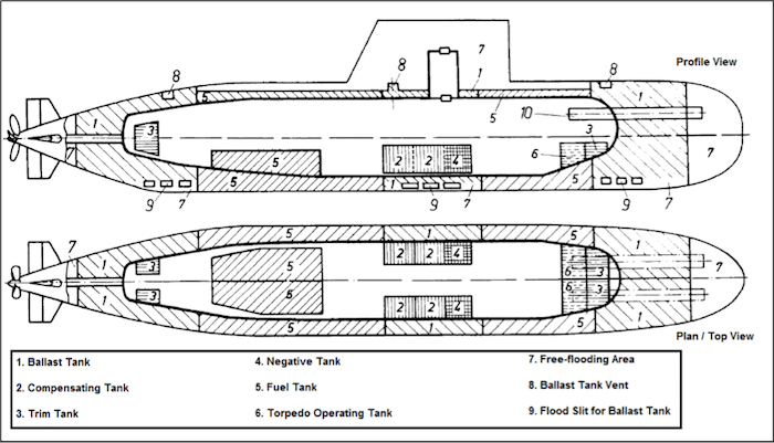
Along with the general arrangement drawing, the tank plan is prepared to locate the position of each tank. Their names, along with the fluid to be carried in them, is specified in the tank plan itself. The capacity of each tank is listed on a separate document called the tank capacity plan.
The following figure shows the tank plan of a double hull diesel electric submarine.
We have studied about the purpose and operation of ballast tanks in detail in the article on submarine stability, hence this topic will be skipped in this article.
Compensating Tank:
Remember discussing how when a submarine is positively or negatively buoyant, it takes actions to maintain a condition of neutral buoyancy by adjusting its weight? This is achieved with the help of a compensating tank, a component uncommon to the traditional concepts of ship design.
Compensating tanks are located at or in close vicinity to the longitudinal center of gravity of the submarine (refer Figure 1). Why? Because, any changes in weight caused at significant distance from the longitudinal center of gravity would create a trimming moment, which is unwanted, as the submarine only needs to adjust its weight. It is located within the pressure resistant hull and takes water or pumps water to the sea depending on the situation to be tackled.
The compensating tank can be emptied by a pump or high pressure air (in case of low noise operation), but for high pressure air to be a feasible option, the tank structure must be pressure resistant to the extent that it can withstand an internal pressure higher than the external pressure.
The following alterations in weight and buoyancy balance are compensated for by compensating tanks:
- When a submarine dives to greater depths, it enters waters that have a varying density than that at the surface. Specific gravity of sea water usually increases from 1.008 to 1.028 with depth. Since density is directly proportional to the buoyancy, the buoyancy increases, therefore making the submarine positively buoyant. To achieve neutral buoyancy, the compensating tank takes water from the sea till the weight cancels out the buoyancy.
- Weight differences are caused due to consumption of stores such as provisions, fuel oil, fresh water, lubricating oil, and other solid stores. Water is taken into the tank to compensate the effect. An interesting thing happens in case of fuel oil consumption. In submarines, as and when fuel oil is used up, the vacant volume in the fuel oil tank is automatically filled with sea water, such that fuel oil always floats on sea water. This is done to prevent free surface effects. But since water takes up the volume of the consumed fuel, the weight of the submarine increases due to this. The compensating tank is also used to offset this change in weight.
- At deeper depths, the high external pressure results in compression of the pressure hull. This reduces the pressure resistant volume of the submarine, which reduces its buoyancy. The lost buoyancy is compensated by releasing water from the compensating tank. Usually, for submarines having maximum diving depth from 200 to 350 meters, volume available for this purpose in the compensating tank ranges from from 0.3 to 0.4 percent of the total pressure hull volume.
A submarine designer considers two special border loading conditions to estimate the capacity of the compensating tank for a particular design. The loading conditions are listed below:
Load-Case 1: At the end of a very long, slow cruise in sea water with maximum density. At the end of a very long and slow cruise, all the consumables like fresh water, stores, food are used up, but relatively sufficient amount of diesel oil is left. The vessel is sailing in sea water of maximum density, which means buoyancy is higher. Both the conditions together require the compensating tank to be filled to its maximum capacity.
Load-Case 2: At the end of a very short, fast cruise in sea water with minimum density. In this condition, the consumables have been partially used up, and the diesel fuel is completely consumed. Since the sea water density is minimum, the buoyancy is least. In such a case, the water required in the compensation tank would be minimum.
In actual case, when a submarine begins its cruise, the volume of water in the compensation tank is somewhere between those corresponding to the two border cases. It has be observed by parametric studies, that compensating tanks usually have volume of 2.5 to 3 percent of total pressure resisting volume of the submarine. This data is also used by designers in the preliminary design stages.
Trim Tanks:
Trim tanks are used to maintain the longitudinal center of gravity just under the center of buoyancy, so that the submarine can be maneuvered to a neutral trim condition. These tanks are equal in size, and are located inside the pressure hull and as far forward and aft as possible so that the trimming moment caused by them is maximised (note the trim tanks in Figure 1). The trim tank system consists of two pairs of tanks, one pair at forward (port and starboard), the other at the aft (port and starboard).
These tanks are interconnected by pipes called trim lines, and the fluid used is called trim water. Trim water is circulated among the forward and aft depending on the required trim condition. Circulation is carried out either by pumps or by low pressure air.
The dimensions of the trim tank are estimated using border conditions determining load-cases and trim conditions and analysing them with the method similar to that of compensating tanks. Trimming effects due to weight shift during firing of torpedoes are also taken into account. For empirical purposes, the volume of trimming water required is 0.5 percent of the pressure hull volume.
An added use of trim tanks is its multi-functional properties, where it can be used as both, trim and compensating tank. In such designs, the trim tanks are provided with flood ports. If say, forward trimming is required, then the forward trim tank is filled and the aft tanks are emptied. If the submarine is to reduce her weight without any change in trim, then both the pairs of tanks are emptied to the required amount. This system offers added advantages with regard to space allocations, as submarines are very space restrictive.
Negative Tanks or Quick Diving Tanks:
These tanks are used as auxiliary means to dive in waves. When a submarine dives in waves, the added buoyancy due to wave action prevents it from diving promptly, and hinders its ability to dive to a deeper depth. As troughs of waves pass across the submarine, the free flooding parts at the topmost deck levels (at the sail and upper deck) remain partially flooded, resulting in failure to dive.
In order to combat this effect, a tank with flood ports is provided at a low level, just forward of the center of gravity of the submarine. Not its location in Figure 1. Flooding this tank would not only add negative buoyancy (or add to the weight), but due to its longitudinal position with respect to the CG, it also trims the bow and helps in quick diving. Due to this, they are also called quick diving tanks. Once the submarine has dived and all the free flood areas are filled with water, the negative tank is drained out quickly by using compressed air.
Torpedo Tanks:
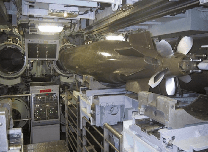
Torpedoes are fired from torpedo tubes that are located at the forward section of a submarine. The weight of each torpedo, in general, is approximately 4 to 5 tons. Hence, once a torpedo is fired, the loss of significant weight from a position away from the CG of the submarine causes a trimming moment, which if not prevented, would hamper the course keeping ability of the submarine. The firing of a torpedo from a submarine involves a sequence of steps to prevent the above.
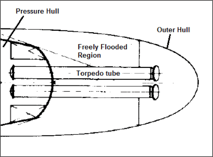
The torpedo tube is a pressure resistant cylindrical structure that has a door at the forward (Muzzle door) and one at the aft (Breech door). A submarine usually has multiple torpedo tubes and can fire more than one torpedo simultaneously. About one thirds of the length of a torpedo tube is inside the pressure hull, and the remaining is located outside the pressure hull, in the free flooded region leading to the forward most point of the outer hull where the front door is located. The portion of the tube in the free flooded region is subjected to external pressure, and is stiffened externally to protect it from buckling.
Step One: First, the aft door is opened, and the torpedo is loaded into the tube. Once the rear door is closed, water from the Weapon Round Tank (WRT) is admitted into the space between the torpedo and the inner walls of the tube. The volume of WRT is sufficient to provide enough water for firing all the torpedoes, without requiring a refill. The location of WRTs is always just above or below the torpedo tubes. Why? If WRTs were located longitudinally away from the torpedo tubes, shifting of water from WRT to the torpedo tubes would have caused unwanted trimming moments, causing the submarine to trim by the bow.
Step Two: The front door always opens in the outer direction, but it cannot be opened at this stage, because at large depths the external pressure is higher than the internal pressure. Hence, the water inside the torpedo tube is pressurized so that the internal and external pressures equalize. Once this is done, the front door is opened hydraulically, and the torpedo is fired.
Step Three: Once the torpedo is fired, the space inside the torpedo tube that was occupied by the torpedo is automatically occupied by sea water that floods in.
Step Four: Though the volume of the torpedo inside the torpedo tube is occupied by sea water, the weight of the sea water is less than the torpedo. In order to prevent a trimming moment, additional water is to be taken in to compensate for the difference in weight. This additional amount of water is taken into another tank called the Air Inboard Vent (AIV), which is located just below or above the torpedo tubes.
Step Five: Now, to reload another torpedo into the same tube, first the front door of the tube is closed, while the tube is flooded. The water in the tube is first drained to another tank called Torpedo Operating Tank (TOT), and then another torpedo is introduced into the dry tube. The TOT is located so as to prevent any longitudinal weight shift. The volume of the TOT is sufficient to carry all the water required to be drained out of the torpedo tube if all the torpedoes are fired.
Hover Tanks:
As and when the submarine dives or rises, its depth-maintaining capability is challenged due to changes in density and resultant compressibility effects. In many stealth operations, naval submarines are required to hover at a fixed depth whilst stationary. In such case, a constant balance of the weight-buoyancy equation is required. This balance can be achieved by a sensor controlled system dedicated to a special tank where water can be taken in when the submarine rises, and water from the same tank can be pumped out when the submarine sinks. This exchange of water is rapid, and is required to be carried out on a continuous basis. Hence a special tank called Hover Tank located outside the pressure hull, is used to cater to this purpose. The reason behind its location in the outer hull (unlike a compensating tank, which is inside the pressure hull) is to maintain its contents at ambient sea pressure so that continuous inflow and outflow of water is possible.
However, in cases where the submarine is to be designed to hover near to the surface, the hover system needs to be more robust so as to compensate the destabilizing effects of wave action.
The other types of tanks used in a submarine are fuel oil tanks, lubricating oil tanks, sludge oil tanks, bilge tanks, and fresh water tanks. They have not been discussed here as their operation and purpose are similar to those of surface ships. It is however, important for a designer to carry out parametric studies of tank capacities of various existing designs before parametrically reaching an estimate for capacity and plan for the tanks of a new design.
You may also like to read – Pathfinder – An Underwater Submarine that Can Run on Ocean Floor
Do you have info to share with us ? Suggest a correction


Latest Naval Arch Articles You Would Like:

Subscribe To Our Newsletters
By subscribing, you agree to our Privacy Policy and may receive occasional deal communications; you can unsubscribe anytime.
What are the special tanks in a “nuclear submarine”?Is the tank plan similar and what are the additional tanks available?
Most of the data is essentially correct but each submarine has small and sometimes major differences even in the same class of submarine due to ship alteration modification design mods in a class and from build modifications and changes occure to the electric electronic hydraulic propulsion and even to location of washers and dryers or showers or toilets lol if you want to know about submarines contact a current or ex submariner