

Marine Propeller Shaft – Design And Construction
The heart of any ship lies in the engine room. Powered by large marine engines usually running on diesel oil of HFO, vessels are able to reach speeds of up to 50 kmph.
The components responsible for actually moving the ship are the large multi-blade propellers fit at the back.
So how does power transfer from the engines located deep inside the hull of a vessel to the propellers at the aft?
The answer lies in an integral mechanical component known as the marine shaft or propeller shaft.
Similar to how driveshafts work in cars, the shafts in ships also transfer rotational power from the engines to the propellers, which convert them into translational motion.
In this article, we will look at the marine propeller shaft and its various components, along with their design and construction, we will also study the working mechanism of these shafts.
How Are Ships Propelled?
The propulsion systems onboard ships power the vessel by converting rotational motion into translational motion. This is similar in theory to the famous Archimedes’ Screw mechanism credited to the Greek Mathematician Archimedes in c. 234 BC.
The rotational energy is provided by two to four marine engines located in the engine compartment of a ship. Both two and four-stroke engines are used depending on the size and required use of the vessel.
The marine engines generally run on diesel, although attempts are being made to turn to energy-friendly alternatives.
Inside the engine, pistons combust the fuel through alternating compression and expansion cycles. The combustion is achieved at ignition temperature and forces the crankshaft to make half a rotation under compression. The expansion phase completes the remaining half of the rotation.
The most commonly used type of marine engine is the reciprocating diesel engine that has a higher efficiency compared to other models. These engines can be classified into three types based on their revolutions per minute (rpm).
The three categories- slow, medium, and high speed have their own benefits based upon the type of ship to be powered.
For instance, large ships require a low speed but high torque propulsion system to power them. For such vessels, a low output speed engine can be selected.
The issue with using slow-speed engines is the large space they take up as compared to the other engines. Thus, a space-effective solution would be to install high-speed engines in the ship, and then reduce the torque before it reaches the propellers.
For this, a gearbox is a very useful component that can be used to manipulate rotational torque transfer. It is attached to the marine propeller shaft and reduces the power transmitted to the propeller.
The slow speed engines pose no problem to the transfer of torque and do not require an additional gearbox. The gearbox in the other speed engines is attached in between the intermediary and propeller shafts.
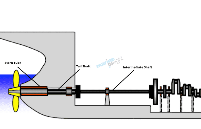
Components of Propeller Shafts
The marine propeller shaft is divided into three main components-
- the thrust shaft,
- intermediate shaft(s), and
- tail shaft
The thrust shaft is the primary shaft emerging out of the engine. It directly receives the rotational motion from the crankshaft and rotates at the maximum velocity in high-speed engines.
For high rpm engines, the thrust shaft is further connected to other components that lie further aft.
The next component is the intermediate shaft. There is no specific restriction on the number of intermediary shafts that a ship can have. However, beyond 2 shafts, it can be difficult to service and maintain. The reason for this is the large catenary force acting on the entire propeller shaft. This force tends to deform and damage parts due to their weight.
When coupled with the large vibrational shocks that act on the shafts, there could be permanent damage to the propeller shafts. Thus, a low number of intermediary shafts are preferred. The only reason to have multiple intermediary shafts as if the engines are located far away from the propellers.
The last part is the tail shaft. It is directly connected to the propellers and lies mainly encased in the stern tube. The tail shaft is connected to the intermediate shaft by a gearbox that manipulates torque transfer. The tail shaft is built to withstand a variety of forces that may act at the stern of the ship.
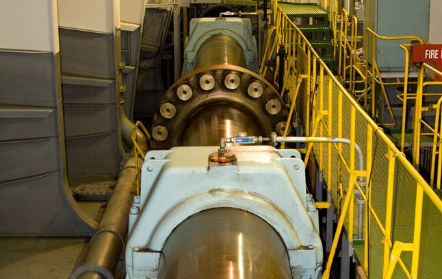
The next component is the coupled bearing that connects two adjacent shafts. The coupling is achieved by virtue of joints that are usually rigid and do not flex. The coupling units are bolted to each other using high strength fasteners that can withstand a large number of vibrational stresses.
Shaft bearings are components that are used to support and bear the load of the shafts. They run along the length of the shaft and ensure smooth rotation. These bearings are constructed differently based on their location.
The last part of the marine propeller shaft system is the thrust blocks. These blocks support the propeller shafts at regular intervals. These blocks play transfer the excess power from the shafts into the hull of the ship.
As the shafts rotate at very high speeds, some amount of vibration occurs. This further leads to jarring shocks that may compromise the structural integrity of the vessel. Thus, using specialized bearings, the shocks can be dispersed over the hull of the ship.
To anchor these thrust blocks to the bed of the ship, a reinforced frame is built. There is a primary thrust block placed aft of the engine crankshaft, that disperses the majority of the shock into the hull girders and structures.
The components discussed above form the large bulk of parts that make up the propeller shafts. In addition, there are a variety of smaller parts such as sealants and bearings that serve different functions.
Design and Construction
The design and construction phase are important as it ensures structural strength. With shaft speeds reaching anywhere between 300 rpm to 1200 rpm, care must be taken to control material fatigue and reduce damages caused to the components of the ship.
The construction of the shaft bearings is important, as this holds the complete weight of the propeller shafts.
There are two main types of bearings- the full case bearing located at the stern, and the half case bearing located at the other positions.
The full casing provides a complete bearing for the weight of the shaft and is an integral part. The reason it is located at the stern is to account for both catenary weight forces, and also to counteract any buckling or reverse thrust forces felt at the aft due to the motion of the propellers. This bearing is also known as the aftmost tunnel bearing, as it encases the shaft just like a tunnel.
The other shafts only account for the weight, and hence do not require an upward casing unit. These bearings must be designed of high strength metals that do not easily buckle or deform under high strains. In addition, low levels of tolerances are expected during the manufacturing stage.
Special bearing pads are fit into slots on the connecting inner face of the bearing, such that it allows for smooth rotation. To lubricate the shaft bearing, an oil dip arrangement is carried out. By coating the rotating surface with oil from an oil thrower ring at regular intervals, a thick coat of lubrication is maintained at all times.
The coolant used to prevent overheating and subsequent damage are water circulated about the shaft bearing. This is stored in specialized tubes that run along the bearing and shaft. Tanks stored above the engine platform house coolant that is circulated around the propulsion machinery and systems.
The thrust blocks are used primarily to dampen and absorb forces from the rotating propeller shafts. These forces are redirected into specialised frames that make up the bed of the engine compartment. The energy in these frames is further distributed into the surfaces of the hull through the hull girders.
The hull girders serve as the framework on which the hull of the ship is constructed. The thrust blocks must be rigidly mounted in place to prevent any form of vibration during the course of the journey. Also, the primary thrust block can either be an independent unit that is built separately or can be integrated into the marine engines itself.
By integrating the block into the engine, it reduces the space requirements and maintenance costs while sailing. However, maintenance, while berthed, can be an issue as it would require opening the engine block casing. The casing that makes up the thrust blocks are built in two parts- an upper half that is detachable, and a lower half that supports the shaft.
The shaft is laid onto the lower block, and the upper half is then bolted into place using specialized fasteners that can absorb shock. To lubricate the rotating shaft, oil is regularly coated on to the rotating surface. This is achieved in a manner similar to that of the shaft bearings.
An oil thrower and deflector are put in place to maintain a constant supply of oil from a storage unit located on the lower half of the thrust block.
The operating temperature is controlled using cooling coils that circulate a chosen type of coolant throughout the block. It also draws coolant from the central propulsion cooling system. To absorb the vibrations and shocks, bearing pads are attached to the blocks.
They can be of two types- tilt pads, or pivotal pads, both of which are held in specialized holders built into the thrust block. The thrust pads transfer energy to the lower half of the casing that is constructed to withstand larger amounts of shock.
A thrust collar is also used to absorb thrust from the propeller shaft. The thrust blocks incorporate integral flanges that primarily help in bolting the block to other surfaces.
For instance, the block can be connected to the gearbox or engine using this flange. It can also be used to connect the engine thrust shaft to the intermediate shafts using these flanges. In case the thrust block is built into the engine block, it is made of the same casing material that the engine base plates are manufactured from.
In addition, they directly use the lubrication and coolant from the engine components itself. The integrated block is similar to the normal thrust blocks in most other features. It is interesting to note that the thrust block is integrated into the engine in most ships, except for the smaller boats that have space constraints.
The shafts themselves must be built from robust materials with high yield strength, and a lower probability of buckling. Each shaft starting from the thrust shaft must be built into small and manageable components that can be disassembled when the need arises.
In addition, seals and stuffing boxes are also built from appropriate materials that can effectively seal the inner working machinery from external water. High-grade materials are a must while manufacturing propeller shafts, as this is very sensitive equipment that needs to handle large forces.
The marine gearbox is an integral component that is attached in between the tail shaft and the intermediary shaft. It is mainly used to manipulate the torque transferred from the engine crankshaft to the propellers located at the stern. It is most commonly used in large vessels that engage a high-speed engine during operations.
The gearbox works just like an automobile gearbox, that uses a system of clutch discs and pads to control torque. Using robust gear arrangements that can withstand large vibrations, the gearbox is an integral part of ships with high-speed engines.
Lubrication is a necessity to prevent friction-related accidents or damage from occurring.
Stern Tube and the Propeller Shafts
Stern tube arrangement refers to the manner in which the tail shaft is borne by the stern tube that is located at the aft of the vessel. The stern tube is a hollow, horizontal tube that serves as the primary connection between the propellers and the rest of the vessel.
Attached to the stern frame, the stern tube acts as a plug at the rear of the vessel. The stern frame is the primary structural member that supports the stern overhang that lies above the propellers and rudder.
The stern tube houses the tail shaft of the marine drive shaft system and serves two main purposes- withstanding load and sealing the entire vessel at the aft portion.
Since the stern tube serves as the primary link between the vessel and the propeller, it must be able to withstand a tremendous amount of force that is exerted by the suspended propellers. In addition, it should provide sufficient room for the propeller hub to actually move without creating friction.
To handle the load, white metal is a commonly used material that can withstand the required loads. Sufficient lubrication is also provided within the stern tube to ensure the smooth functioning of the entire marine propulsion system.
Along with supporting the structural weight and forces of the propeller, the stern tube also needs to be able to effectively seal the vessel. It prevents water from entering through the aft and achieves this by using a combination of seals along its length. The stern tube has two main seals located at its aft and fore regions.
This serves as dual protection against any possible leaks that may occur over long periods of time. These seals can be of three main types- stuffing boxes, lip seals, and radial face seals. Stuffing boxes are built out of a variety of packing materials that are used to plug the stern tube.
Lip seals are gland seals that are used to prevent lubricants from seeping out into the water. They also serve the dual purpose of preventing water from entering the stern tube. Lastly, radial face seals extend radially out from any points of ingress and use a spring system to seal the entire structure. They are composed of two main parts that join to completely seal the rear portion.
The stern tube plays an important role in marine propulsion since it absorbs and dampens a considerable amount of power away from the propeller. In an effort to completely seal the stern section of the ship, it may also hamper the rotational abilities of the propeller shafts.
This would be counterproductive and would create a large amount of stress within the hull of the ship. Thus, being able to effectively seal the aft region without affecting the performance parameters is a major necessity in naval architecture and engineering.
Do you have info to share with us ? Suggest a correction

About Author
Ajay Menon is a graduate of the Indian Institute of Technology, Kharagpur, with an integrated major in Ocean Engineering and Naval Architecture. Besides writing, he balances chess and works out tunes on his keyboard during his free time.


Latest Naval Arch Articles You Would Like:


Subscribe To Our Newsletters
By subscribing, you agree to our Privacy Policy and may receive occasional deal communications; you can unsubscribe anytime.
Thank you very much for this article. You explained marine propulsion and shaft in a clear manner.
Thank you very much for this information