

Superstructure Of Ships – Requirements For Design & Types Of Loads Acting
Going back to the fundamentals, we all know that a ship, for all general purposes has two principal structures; the hull and the superstructure.
Now the term ‘superstructure’ is a very inexplicitly used one as one often calls it interchangeably as bridge or deckhouse. However, subset differences do exist which we will discuss thereafter.
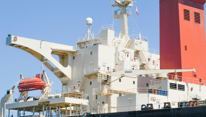
Succinctly, to sum up, our main point of discussion will be regarding the structures lying above the hull of the ship which houses the accommodation, offices, the navigation bridge, the signalling and communication units, utility spaces and multifarious electrical and electronic system areas, which are indispensable to the operation and the functionality of the ship as well as the sustainability of crew.
Differences Between A Ship’s Superstructure And A Deckhouse
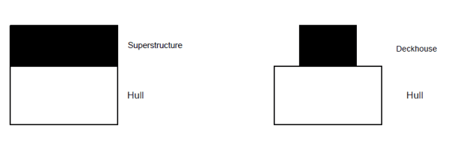
Though more or less the same, there are subtle differences between a superstructure and a deckhouse of a ship. A superstructure extends laterally to the end extremities of the main deck, i.e. its side walls are an extension of the side shell plating of the main hull.
On the other hand, a deckhouse is placed inward from the edges and their ends are welded to the main deck plate. Typical superstructures are poop, bridge, and forecastle. (Learn more about different types of decks here)
This difference, however, has significance from the structural point of view.
In our discussion, we use superstructure interchangeably for deckhouses, bridges and superstructures.
Before delving into the details of superstructure design, let us first overview the main critical design philosophies behind it.
• The design background of a ship’s superstructure is completely different than that of a hull. The hull of a ship directly interacts with water and therefore is the most crucial consideration to a designer. Thus, the hull has to be designed from a pure hydrodynamic point of view. This is intrinsically related to the resistance, propulsion and hence, the powering proportions of a ship. Hardly do we observe a ship which is blandly a box-shaped one. Stability of ship and ease of construction are also key deciding factors. Designing the precision lines of a hull form keeping in view all these aspects is the bedrock of any form of ship design.
• Structurally, a hull is vastly different than a superstructure, as it goes without saying that the strengthening considerations to withstand the seas will be of much more concern than the case of a superstructure which lies above. They hardly have contact with the water (except in exceptional cases like clement weather conditions or hefty wave surges where effects like ‘green water’, ‘wave slap’ which momentarily affect the superstructure.)
• Moreover, all the principal utility spaces for any vessel are located within the hull. For any kind of cargo ships, it is the cargo spaces; for passenger ships, a majority of the passenger spaces; for defence vessels, its main armoury and mechanisms, just to name some. Major machinery spaces (including the engine room) are located inside the main hull. Tanks for various purposes like ballast, fuel bunkers, lubes, fresh water etc. are all housed in the hull. Thus, the loads from all these entities also dictate the strength requirements of the hull as opposed to superstructures.
• However, the global load response is an important aspect to ponder upon regarding superstructures. As any kind of superstructure or deckhouse is welded to the hull, it is a typical consideration in the global longitudinal bending considerations due to weight-buoyancy indices and waves bending moments just like the hull girder.
Requirements Of A Good Ship Superstructure Design
A proper superstructure design should cater to all of these following features:
- Operational requirement fulfilment in terms of adequate volume
- Provision of adequate deck space and height.
As highlighted in the first point, a superstructure operationally fulfils all its purposes. So, while laying out the design plan of superstructures or deckhouses, the designer should carefully plan the deck space area required to house all its functionalities.
Another crucial aspect is the height of superstructures. The height should suffice enough to allow for proper ‘line of sight’ as required for navigation purposes also based on the length and type of the vessel. Moreover, the height should cater exhaustively to all the service requirements but should not jeopardize the stability of the vessel, i.e. should be within the design stability limits of the vessel.
-Desired Stability: This is basically related to the previous point. One of the most crucial aspects of the superstructure erection is the perspective of stability. So, based on requirement and stipulated regulations, one must be very careful in designing a superstructure such that there is an acceptable centre of gravity and intact stability of the vessel is not compromised.
– Durability, reliability and less maintenance
– Structural soundness, not only for main loads but also for secondary operational loads
– Ideally should contribute to the longitudinal strength of the vessel
– Proper connection in terms of joints or proper welding procedures with the underlying deck plating. This is mainly due to the possible development of localised “stress concentrations” in large numbers, which is inevitable.
– Proper resistance to distortions and lateral stresses
– Endurable to adverse weather conditions (thunderstorms, rain, and ice) and also up to a certain extent, the case of green water and wave slaps.
Loads Acting On A Superstructure
Often there has been an ambiguous school of thought from the structural point of view, whether it is beneficial or detrimental.
Let us first see from the beneficial perspective.
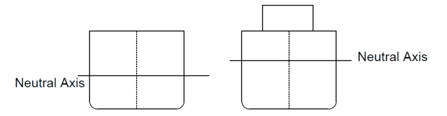
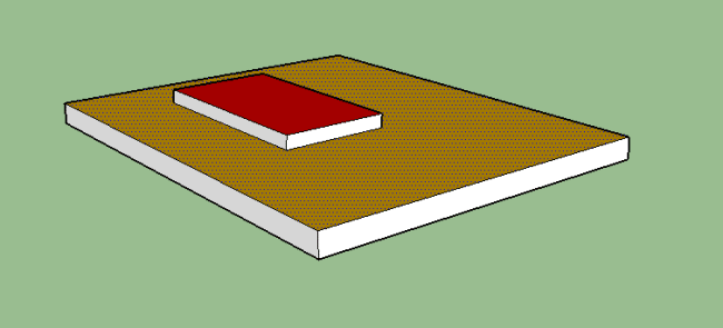
A superstructure attached to the main hull can be viewed as a beam superimposed on another acting as a ‘composite 2-beam system’. The main longitudinal load-bearing capacity of any structure like a hull can be deduced from the Section Modulus.
This, in turn, depends on a very crucial factor which is the position of the neutral axis. So as illustrated in the following figure, in presence of a superstructure or a deckhouse above the hull, the neutral axis for the entire ship’s transverse section goes above. This means an increase in the section modulus as obvious implying an increase in the longitudinal strength.
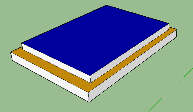
However, this is not always the case. From the physics of composite beams, it can be seen that a beam or any other member in conjunction with the other can contribute to its longitudinal strength only if its length is comparable to the other. This analogy can be well illustrated with an example.
Suppose if you take 2 textbooks of similar size and place it one above the other. Then you try to bend them together. It is observed at once that there is a greater effort required to bend them as compared to a single book. On the other hand, if you place a small and narrow notepad (assuming the same page thickness) over one of the books and try to bend, there is a noticeable tendency of bending. The notepad negligibly contributed to the overall strength. Moreover, it may also try to remain stagnant or tend to bend in the opposite direction.
Similar is the case of superstructures. The length, beam and the position of the superstructure dictate up to a great extent, their response behaviour to loads which we discuss subsequently.
Related Reading: Loads acting on aft and fore region of ships
First and foremost, there is a need to list out the main loads acting on a superstructure.
- Loads transmitted from the ship’s hull, including both local and global loads
- Loads due to wind and waves (wave slaps overboard and green water)
- Loads due to the gravitational and inertial effect on equipment
- Loads due to weapon effect (for warships)
The first load case has been briefly discussed previously. The longitudinal bending stresses onto the hull girder are transmitted directly to the superstructure via the welds or joints in between. This is known as the hull bending stress flow.
Now there are two principal factors coming into play at this juncture:
- Length of the superstructure
- Location with respect to the strength bulkhead deck
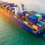
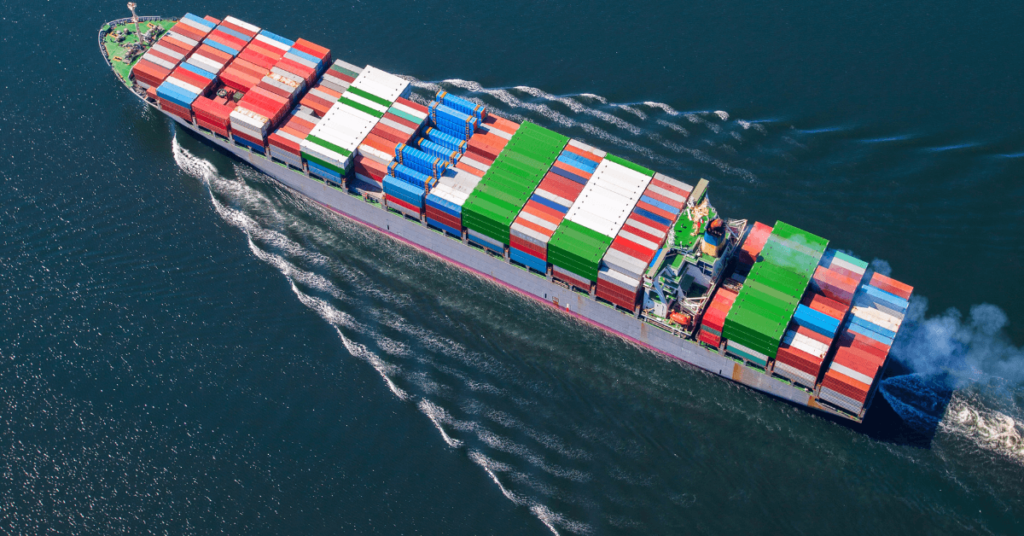
Now, the length of a superstructure varies for different ships. For example, a bulk carrier or a tanker has a short aft superstructure whereas a passenger ferry has a long predominant superstructure almost occupying the entire span of the hull length.
Related Reading: Understanding design of container ships
With adherence to the longitudinal bending of the hull girder, this is of utmost importance. Have you wondered why? The answer lies in the beam bending analogy of the ship.
For practical purposes, when we used to compute the structural scantlings in the basic design phase, the hull girder was treated as a prismatic beam.
Now while analysing the hull-superstructure interaction, we may treat the vessel as a composite beam assembly where the hull and the superstructure are two discrete entities joined together as one. So, when the hull girder is subjected to longitudinal loading, the bending stresses are transmitted to the superstructure.
Here the above mentioned 2 factors come into play.
If the superstructure is long, the loads from the hull are more or less completely transmitted to the superstructure. This can also be analysed in terms of the radius of curvature. If the hull and the superstructure are of comparable length, the latter would take up the same radius of curvature during bending. Here the composite slender beam analogy can be implemented where they bend as a single entity due to the induced bending moment.
Related Reading: Design Of Ship’s Bottom Structure
Since complete load transfer takes place, the superstructure will act as a part of ‘hull girder bending’. A high value of longitudinal bending stress is induced. In order to allow the superstructure to take up the same deflection (deformation) as the hull girder, vertical forces would be generated, prominently in the superstructure sides as a reaction.
Shear forces would obviously generate horizontally in the interface between the superstructure and the hull. Moreover, the high shear stresses acting on the ends because of structural discontinuity would be less if the length of the superstructure is long due to higher shear area coupled with the physics of the ‘shear lag effects’.
In other words, the larger the distance of the ends of superstructure from the midship, the lesser are the effects of end distortion.
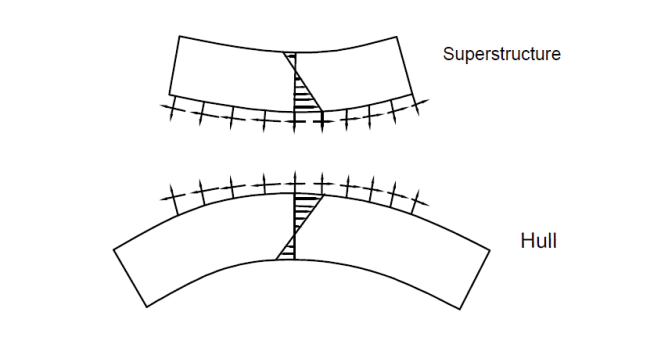
On the other hand, if the superstructure is short enough, the loads from the hull girder are not completely transferred to the superstructure. Here the radius of curvature of the superstructure is different as compared to the main hull. So, it does not contribute to the hull’s longitudinal bending. In this case, the superstructure tends to separate away from the hull structure. Henceforth, the separation forces predominate the bending stresses in this case as shown in the figure below.
Related Reading: Why do ships fail at midship region?
The vertically acting forces are these separation forces which make the superstructure appear to bend in a sense opposite to that of the main hull girder. Thus, the superstructure tends to vertically ‘detach’ itself from the superstructure. The superstructure basically tends to bend in an opposite sense as compared to that of the main hull.
The illustrated effect is more profound if the superstructure/deckhouse location is closer to the midship region where high bending stresses come into play.
Are you still with us? Hope you got the fundamentals until now.
In the next article, we will learn more about stresses and also find out about superstructure efficiency.
Disclaimer: The views mentioned above are of the author only. Data and charts, if used, in the article have been sourced from available information and have not been authenticated by any statutory authority. The author and Marine Insight do not claim it to be accurate nor accept any responsibility for the same. The views constitute only the opinions and do not constitute any guidelines or recommendation on any course of action to be followed by the reader.
The article or images cannot be reproduced, copied, shared or used in any form without the permission of the author and Marine Insight.
Do you have info to share with us ? Suggest a correction


Latest Naval Arch Articles You Would Like:
Subscribe To Our Newsletters
By subscribing, you agree to our Privacy Policy and may receive occasional deal communications; you can unsubscribe anytime.
Web Stories

About Author
Subhodeep is a Naval Architecture and Ocean Engineering graduate. Interested in the intricacies of marine structures and goal-based design aspects, he is dedicated to sharing and propagation of common technical knowledge within this sector, which, at this very moment, requires a turnabout to flourish back to its old glory.
An interesting and well written artilcle.
However, there is one small error you may wish to correct. ‘clement weather conditions’ should be ‘inclement weather conditions’.
@Nick:
Thank you for the suggested correction ??