

Common Welding Methods And Weld Defects In Shipbuilding Industry
Welding is one of the most widely used hot-work processes used in the shipbuilding industry. The development in welding technology has enabled the industry to produce perfectly watertight and oil-tight joints. Welded joints as compared to riveted joints are much easier to produce and they reduce the cycle time of the project. Welded joints have also resulted in reduced steel weight and require less to negligible maintenance compared to rivet joints. The major contribution of welding technology to the shipbuilding industry is the possibility of producing smooth hull surfaces, therefore reducing the bare hull resistance and power requirements considerably.
Welded joints as compared to riveted joints are much easier to produce and they reduce the cycle time of the project. Welded joints have also resulted in reduced steel weight and require less to negligible maintenance compared to rivet joints. The major contribution of welding technology to the shipbuilding industry is the possibility of producing smooth hull surfaces, therefore reducing the bare hull resistance and power requirements considerably.
The three main welding techniques that are used in a shipyard are as follows:
- Arc Welding
- Gas Welding
- Resistance Welding
Arc Welding:
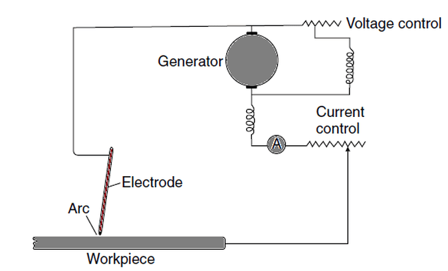
The fundamental principle of arc welding is to connect a metal electrode to an electrical power supply, forming a closed circuit if the plate is touched with the electrode. When the electrode is raised from the plate by a few millimetres, the electric current jumps the gap and an electrical arc is created at high temperature. This results in melting the parent metal and the metal in the electrode, allowing both the metals to fuse.
Arc shielding is an important aspect of all arc welding processes. In order to prevent oxidation the fused metal, the arc is shielded from the ambient air, and contact with oxygen and water vapour are cut off. The two mostly used shielding techniques used by shipyards are as follows:
- Slag Shielded Arc Welding
- Inert Gas Shielded Arc Welding
Slag Shielded Arc Welding:
Slag is the residue left over after the parent metals and the electrode metal has fused. It forms a layer over the arc and the welded joint, protecting it from oxidation. The presence of slag stabilises the arc, providing a better weld quality. There are three main Slag Shielded Arc Welding processes used in shipyards:
• Shielded Metal Arc Welding: The filler metal of most electrodes used in the shipbuilding industry is mild steel. Mild steel drawn in form of rods are coated with a mixture of mineral oxides, fluorides, silicates, hydrocarbons, and a liquefied binder which binds them together to form a solid envelope around the fuller metal. This coating forms the slag, stabilises the arc and prevents oxidation of the joint. Shielded metal arc welding is used in the fabrication of panels, grillages, tank units, etc. They are used in manual arc welding processes, and can help achieve welding at different positions, namely:
- Down hand welding.
- Overhead welding.
- Vertical welding.
Positional flexibility with this welding process makes it the only welding process used to weld the underside of overhead deck plates.
• Submerged Arc Welding: In this welding process, the arc is sparked and maintained under a blanket of granulated flux which is laid on the weld joint before the arc strikes the joint. Follow the figure to understand it further.
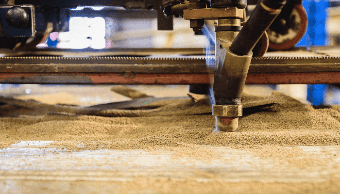
A hopper containing granulated flux runs along the length of the weld joint. It deposits a blanket of flux on the joint. The hopper is followed by a trolley which holds the filler metal electrode. The electrode is continuously fed by rollers driven by a drive motor, and the feed rate of the electrode is set to such a value so that the electrode tip is always submerged within the flux. The arc is hence generated within the layer of flux, allowing complete insulation from the environment.
The speed of movement of the trolley, the feed rate of electrode and amount of flux on the joint are very important parameters that are pre-decided depending on the thickness of the plates, the material of the parent metal, and quality of weld joint to be achieved.
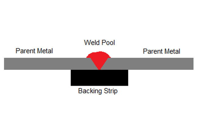
Submerged arc welding is the most commonly used downhand welding method in the shipbuilding industry, owing to its arc stability and quality of joint. Since most of the joints are welded on one side, a backing strip made of ceramic material is placed under the joint, to prevent the flow of weld bead from the other side.
• Stud Welding: This welding process is used when a stud or bolt is to be welded to a parent metal. The stud is fixed at the muzzle of the stud welding gun. When the gun is fired, the stud is struck onto the metal. The high velocity of the stud along with the completed electric circuit generates the arc which fuses both the metals. Once the stud is driven into the metal, the electrical supply is automatically cut off. Granular flux is contained at the end of each stud to provide insulation from air.
This process is used for fastening insulation panels to bulkheads, wooden flooring onto deck plates.
Gas Shielded Arc Welding Processes:
Gas shielded arc welding processes use a blanket of a gas, instead of flux, to provide insulation to the arc against the ambient environment. They are used extensively in shipyards to welding the comparatively lighter structures.
• Tungsten Inert Gas Welding (TIG): In this welding process, the arc is created between a non-consumable tungsten electrode and the parent metal plates. The tungsten electrode is surrounded by a nozzle that maintains a continuous flow of an inert gas around the arc. This inert gas shields the arc from oxygen, hence stabilising it, and preventing oxidation of the weld pool. A filler rod is introduced into the arc, which helps in the fusion of the two metals. The inert gas used in this process is usually Argon. TIG welding is preferred for plates of thickness usually less than 6 to 8 mm.
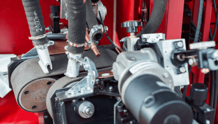
• Metal Inert Gas Welding (MIG): Metal inert gas welding is, in a way, an advancement on tungsten inert gas welding, where the electrode is a consumable metal wire.
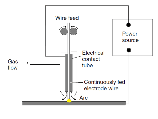
The welding torch consists of an electrical contact tube which connects the electrode wire to the power supply. The electrode wire is continuously fed into the nozzle by a pair of driver rollers. It passes through the electrical contact tube. The flow of an inert gas is maintained into the welding torch through a separate line leading into the torch. It creates a blanket of inert gas around the stabilized arc.
Carbon dioxide is the most widely used inert gas for this purpose. MIG welding has been widely used in welding of aluminium deckhouses and spherical membrane tanks in liquefied gas carriers.
We will also discuss some of the other welding processes used in the shipbuilding industry for specialised purposes:
• Plasma Welding: This is similar to the process of TIG welding, except for the fact that the tungsten electrode is separated from contact with the plasma. Plasma is shot into the weld joint, which increases the temperature and provides shielding effect. This welding process is used for thinner metal sheets, most usually, in sheet-metal workshops in a shipyard.
• Laser Welding: Laser welding processes are used in advanced shipyards, and since this requires minimum heat input, the welding distortions (we will discuss this in detail soon) produced are minimised. The source of the laser in this process is either carbon dioxide or Nd:YAG (neodymium yttrium aluminium garnet) crystals.
• Thermit Welding: Thermit welding is more of a typical fusion process which is used to hold together large steel sections or forgings, for examples heavy sections of the stern frame of a ship. The heating in this welding process is achieved from a mixture of aluminium and iron oxide.
• Friction Stir Welding: This is a widely used process in shipyards, the source of heat being friction created between the rotating pin and the parent metal plates. The advantage of this welding process is its feasibility in the vertical direction, which makes it possible to friction weld but joints of side shells between blocks of a ship.
Welding Practices in the Shipbuilding Industry:
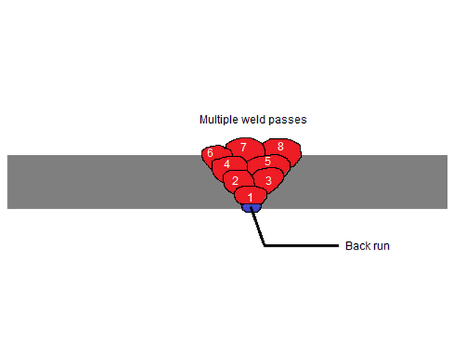
• Multiple Passes: When plates of high thicknesses are welded (usually more than 5 to 6 mm), a number of welding passes are required to fill the gap between the plates in order to achieve full penetration. In cases where fillet weld is carried out with high deep bevels between the plates, multiple passes become necessary.
The following figure shows the cross section of a multi-pass butt weld joint consisting of eight passes. Note that the first pass is not sufficient to provide complete penetration till the root of the joint. In order to overcome this, a back run is provided. Back run is an additional welding pass carried out from the opposite side of the weld joint before the main passes are laid. The excess material is then gouged out to obtain smoothness and finish.
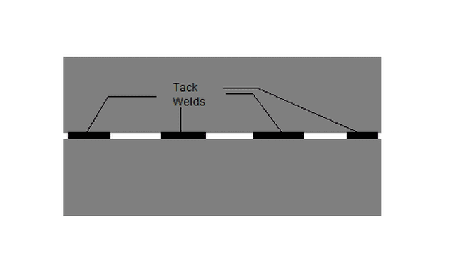
• Tack Welds: Before two plates are welded, they are tack welded at regular intervals along the length of the weld joint. This is done to hold the plates in position, preventing them from opening apart due to heat gradients during the main welding pass. Tack welds are short runs of weld made at intermittent distances, and the electrodes used for tack welds are same as that used in the main runs.
• Welding Sequences: Welding sequences are prepared, taking into considerations the distortions that would result. When a weld run is completed, the cooling is not uniform along the length of the weld. This results in the development of stresses that pull the plates closer at one end and pull them apart at the other. In some cases, especially long butt welds, shrinkages occur along the weld length, resulting in warping of the welded plates. In order to minimise these, the sequence and direction of each weld are pre-decided and listed on the welding sequence document of the corresponding structure. They are prepared for welding at all stages, right from the fabrication of panels, units, blocks, to the erection of the fabricated structures on the berth.
Weld Defects and Weld Quality Testing:
Every weld joint is inspected by a team of trained inspectors for weld defects. Welding defects may arise due to lack of skill in welders, use of incorrect materials, or improper welding methods and ambient conditions.
The most common weld defects are as follows:
1. Lamellar tearing.
2. Crater cracks.
3. Inadequate cross section or insufficient penetration of weld pool.
4. Underbead cutting.
5. Gas entrapment within the weld pool.
6. Slag inclusions within the weld joint.
7. Overlaps.
8. Undercuts.
9. Lack of reinforcement.
10. Excessive reinforcement or extra deposition.
11. Lack of fusion within the weld pool.
The most commonly used non-destructive methods of weld quality inspection are discussed below.
• Visual Inspection: Visual inspection is carried out by a trained inspector, in which any surface defect is detected by the aid of a naked eye. Surface slag deposition, the incorrect shape of weld beads, incorrect alignment of plates and excessive reinforcement on the surface can be detected by visual inspection. However, all the undersurface defects require other methods of inspection that are discussed further.
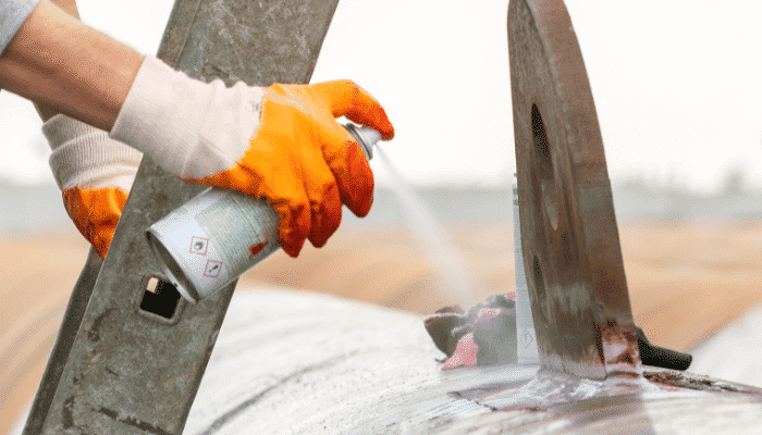
• Dye Penetrant Inspection (DPI): Surface cracks are most commonly detected by the dye penetrant method. First, the weld joint is cleaned so as to remove any slag or unwanted material on the surface of the welded joint. A layer of developer is sprayed over the weld joint. This is white in colour and aids the eye in the further steps. The dye is then sprayed over the weld joint. The colour of this dye is usually bright red because it is most noticeable to the human eye. After a sufficient waiting time, the weld joint surface is cleaned. The cleaning removes all the dye from the surface, however, the layer of developer remains. In the case of presence of any surface crack, the dye seeps in, hence after cleaning of the surface, the crack clearly appears red. It is in order to notice this with clarity that the developer is applied. The presence of any red lines indicate surface cracks, and corrective measures are hence taken.
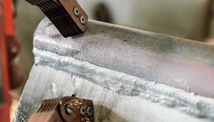
• Magnetic Particle Testing: Smaller cracks are not noticeable in DPI tests. However, magnetic particle inspection reveals them clearly, due to the change in magnetic field at the cracks. In this test, the magnetic powder is spread on the weld joint to be tested. The alteration in magnetic field at a crack on a ferrous material, the magnetic particles accumulate along the length of the cracks, forming clusters at their vicinity. This provides a clear indication of surface cracks. The image below shows two regions of clusters of small cracks on a pipe.
• Radiographic Testing: The method of radiographic testing is based on a fundamental principle of subjecting the test piece to a beam of radiation from one side, and capturing or recording the emitted radiation on a photographic plate on the other side of the test piece. This is where radiographic testing comes of great use in detection of subsurface weld defects. Any obstacle within the weld joint would change the radiation density in that area, which would be reflected on a photographic plate. Hence radiography is basically used to test the consistency of the weld metal. The following figure shows the detection of a surface and subsurface discontinuity on a photographic film.
Both X-Rays and Gamma rays are used in radiography tests. Reading and interpreting weld defects from radiographic plates required skilled and experienced personnel who are specialised for the job.
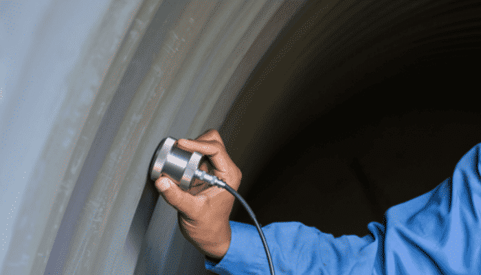
• Ultrasonic Testing: Ultrasonic testing uses the same principle as that of radiographic testing, but with two major differences. First, use of ultrasonic radiations eradicates the health hazards related to harmful X-Rays and Gamma rays used in radiographic tests. Secondly, the recordings need not be processed as much as that of radiographic tests, because they are obtained in graphical format as discussed below.
A probe sends a beam of ultrasonic waves into the weld joint. The reflected waves are obtained on a graph on a computer screen. The first spike in the graph would be due to the reflection from the upper surface of the weld. The second spike (usually of lesser amplitude from the first) represents the wave reflected from the back (other) side of the plates. A presence of an obstruction within the welded area would also reflect some waves back to the probe, therefore cause the third spike of reduced amplitude than the spike caused due to the back side. This spike, however, appears before the spike from the back side appears. Added to that, since a number of waves now reaching the back side of the plates is reduced, the presence of a third spike due to a weld defect would also cause a reduction in the amplitude of the second wave, as shown in the schematic diagram below.
The above illustration also helps us understand how ultrasonic testing can not only be used to detect the presence of a weld defect, but also detect the location of the defect. If the thickness of the plate is ‘E’, the distance between the spikes due to the front side and back side of a weld joint without defect would be ‘E’ on the linear distance scale on the graph. Similarly, the distance between the spike due to the upper surface and the spike due to the weld defect would reflect the depth from the surface at which the defect is located.
It is this property of ultrasonic testing that makes it the most widely used non-destructive
testing method for major welded structures in shipyards.
Today, classification societies have laid out norms not only on methods of welding but also on the standards of electrodes to be used for each type of joint, depending on its location on the ship. Major research works are being undertaken to predict the nature of weld distortions so as to develop welding methods to prevent rectification of structures due to welding induced stresses. It is this vast scope of research that makes welding an interesting field of study for researchers.
Disclaimer: The authors’ views expressed in this article do not necessarily reflect the views of Marine Insight. Data and charts, if used, in the article have been sourced from available information and have not been authenticated by any statutory authority. The author and Marine Insight do not claim it to be accurate nor accept any responsibility for the same. The views constitute only the opinions and do not constitute any guidelines or recommendation on any course of action to be followed by the reader.
The article or images cannot be reproduced, copied, shared or used in any form without the permission of the author and Marine Insight.
Do you have info to share with us ? Suggest a correction


Latest Naval Arch Articles You Would Like:

Subscribe To Our Newsletters
By subscribing, you agree to our Privacy Policy and may receive occasional deal communications; you can unsubscribe anytime.
Web Stories


I love marine engineering
Saurav Great about your vision and passion and thanks for your support for learner begginers
Figure 9: Dye penetrant inspection. (Source: wikipedia ) is wrong. No. 1 is not applying of developer, it is to show the surface-breaking crack that is not visible to the naked eye. If you check the original figure from Wikipedia, you will find it.
Amazing! the article is full o knowledge and so smartly explain. As the ship is made of metal only and from it stay 24 hours in the sea. So because of the chemical reaction, the ship might get easily corrode so to maintain it’s very difficult. A small ship can be maintained but the huge ships are not to possible. But the problem solution got. Thanks for the article. As the diagrams and all have explained very excellent.
VERY IMPRESSIVE AND HELPFUL ARTICLE
A small ship can be maintained but the huge ships are not to possible. But the problem solution got.
I like that you mentioned that the techniques nowadays are being improved to ensure that there will be no mistakes in the future. I will share this information with a friend of mine so that he will have peace of mind that the project will be of success. He just need to have some parts of their shop welded because they have been damaged when the hurricane struck last weekend.
Is there any dissimilar welding present in ships then what types of dissimilar metals are used for that welding?
As from my view the most common type of welding is arc welding which joins two metal parts equally as there are more types of welding but this type of welding is often used by welders and you can see in many parts where welders joint the metal parts with its help. As the form of arc welding is improved, it is applied in industrial robot integration as well.
thanks for this post