Understanding Stability of Submarine
You will soon understand why we did not discuss the stability aspect of submarines in the previous article itself, rather had focused on familiarising ourselves with the main parts of the submarine. That is because, design in itself is a complex and long process that includes both understanding and implementation. It is hence recommended that you read the previous part prior to this to understand submarine design basics. This article also assumes that you are familiar with the basic concepts of ship stability.
The most unique feature of submarine design stability is that unlike ships, submarine stability is studied at two conditions:
- Surfaced Stability (when part of the submarine is above the waterline), and
- Submerge Stability (when the submarine is completely submerged, and no part or appendages are above the waterline).
The fundamentals of floatation and Archimedes’ Principle are used to arrive at the equation of floatation of a submarine, that is, in either of submerged or surfaced condition, the weight of the submarine is equal to the buoyancy force acting on it. This also implies that for a surfaced submarine to submerge, the total weight of the submarine has to increase. It is only then that in submerged condition, the buoyancy on the volume of the submarine above the waterline (in surfaced condition) can be balanced by the additional weight.l
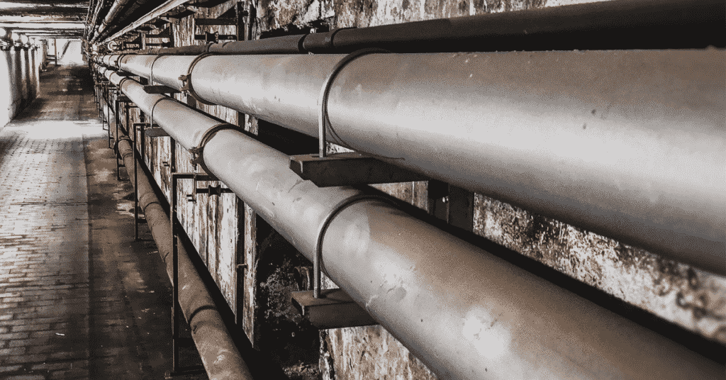
So how weight added to the submarine? Remember Main Ballast Tanks (MBTs)? Sea water is taken into these tanks, and this added weight of the sea water increases the weight of the submarine, which allows the submarine to dive.
We will first look into the diving and surfacing techniques before going further into stability and understanding how submarine works.
Diving and Surfacing of Submarines
We will look into the parts and components of a main ballast tank to understand the sequence followed in diving and surfacing. The following figure illustrates a transverse section of an MBT.
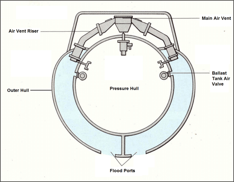
The two vital parts of MBTs are the:
- flood ports, and
- air vents
Flood ports are openings at the bottom most position of the outer hull that allows water to enter and leave the tank.
Air vents risers, one on port and starboard side each, are routed from the tank to the main air vent at the top of the pressure hull. For a surfaced submarine to dive, the air vent at the top is opened. This allows the air in the tank to escape, and sea water floods in from the flood ports below. The ballast weight now added helps the submarine to dive in.
Now, the operating depth of most modern submarines is 300 to 450 meters. For a submarine to surface from that depth, it first uses its hydroplanes to reduce its depth upto 3 to 4 meters below waterline. Once it cruises at that depth, high pressure air at approximately 15 bar is introduced into the tank through the air valve. The air pushes the water out of the tank through the flood ports. Once this weight is lost, the submarine is now positively buoyant and rises up to surfaced condition.
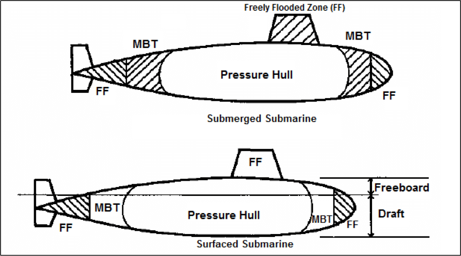
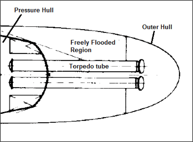
The figure below shows the flooding conditions of the MBTs and freely flooded regions (forward dome, aft cone, and the sail) during submerged and surfaced conditions.
Surface Stability of Submarines
A submarine in surfaced condition has to satisfy the same stability principles as that of a surfaced ship. The primary requirement in surfaced condition is that, it should remain afloat even after any kind of damage. Which means, there should be a significant volume of the hull above the waterline. This is called the Reserve of Buoyancy (ROB). The figure below represents the volume of the hull that contributes to reserve of buoyancy.
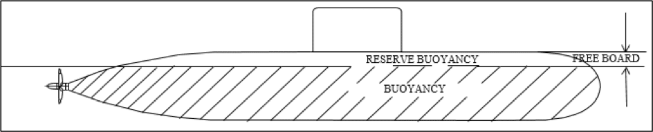
Understanding the concept of ROB is very vital to a designer, as in, it helps the designer to arrive at a primitive value of the required volume of MBTs for a given pressure hull volume.
The ROB of a submarine is basically the ratio of the effective volume of all the MBTs to the volumetric displacement of the submarine in surfaced condition. The effective volume is the total “blowable” volume of the tanks (i.e. volume of the tank required to be filled to submerge the submarine). And just like surfaced ships, the surface displacement of the submarine is the weight of the submarine minus the free flood water. Now note in Figure 2, that in submerged condition, the only structure providing buoyancy is the pressure hull. Hence, the weight of the submerged submarine minus the free flood water is equal to the buoyancy on the fully pressure hull.
The above definition and analysis of ROB helps us to arrive at the following relation between the ROB and pressure hull volume to achieve the total blowable volume of MBT required.
The amount of ROB that needs to be incorporated in a design depends on the size of the submarine. Smaller submarines will have lesser freeboard, hence the larger ROB is desirable in smaller submarines than larger ones. ROB in submarines usually range from 10 percent to 20 percent, and the value can reach higher limits in case of double hull submarines.
The transverse stability analysis of a submarine is similar to that of a surface ship, as both follow the same hydrostatic principles. The stability criteria of the submarine in surfaced condition is its metacentric height (GM), as shown in the figure below.
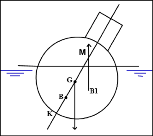
In the above case, when the surfaced submarine heels, the centre of buoyancy (B) shifts to a new position (B1). The metacentre (M) if above the centre of gravity, creates a righting moment that brings the submarine back to upright position.
Submarines are very weight sensitive, as in, during the entire operation of a submarine, all operations are to be carried out in such a way so that there is minimum shift in the longitudinal position of the centre of gravity. As shown in the figure below, the slightest change in longitudinal centre of gravity will cause a trimming moment that results in a drastic decrease in the water plane area. Since the longitudinal metacentric height will be proportional to the on the waterplane area, any trimming moment rapidly reduces the metacentric height.
Submerged Stability of Submarines:
When the MBTs are blowed and pressed full, the submarine dives, and now enters an environment of operation that is not familiar to most engineers and designers of surface ships. The first property of a submerged submarine is its ability to execute motions in all six degrees of freedom. The minimum and maximum allowable depths are called ceiling and floor. The above properties are similar to that of an aeroplane, but there is one aspect that makes a submarine unique, that is, unlike an aeroplane, a submarine does not depend on forward motion to support its weight. The fins on a submarine are only used to invoke lift forces that help it to alter depth. But a submarine can remain static in a submerged condition without any forward motion, and without the help of its fins, why?
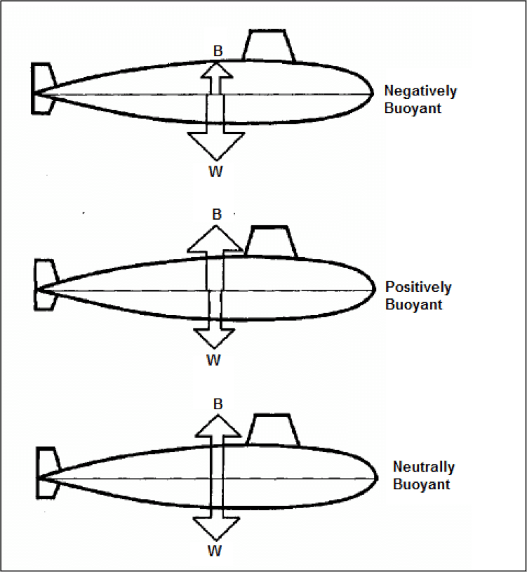
The answer lies in the weight-buoyancy relation maintained in submarines. When the weight of the submarine is more than the buoyancy, it sinks until any corrective action is taken to reduce the weight or increase the buoyancy. This condition is called Negatively Buoyant.
Similarly, when the weight is less than the buoyancy, the submarine is said to be Positively Buoyant, and floats up until corrective action is taken to increase the weight. But all submarines in submerged condition operate on a condition that lies between the above two, such that the weight and buoyancy are always equal. The submarine, in this condition, is called Neutrally Buoyant. How a submarine achieves neutrally buoyant, is something we will study in further articles of this series.
The transverse stability criteria of a submarine changes significantly in submerged condition. Since any angle of heel in a submerged submarine does not cause a change in the underwater volume, the centre of buoyancy remains unchanged. In other words, the metacentre of a submerged submarine coincides with the centre of buoyancy. Hence, the metacentric height (GM) is transformed to (BG), as shown in the figure below. Now, there can be two cases here. One, when the centre of gravity (G) is below the centre of buoyancy (B). Two, when the centre of buoyancy (B) is above the centre of gravity (G).
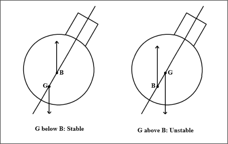
As shown, when the G is below B, a righting moment is developed, which brings the submarine to its upright position, whereas, when the G is above B, the submarine capsizes. It is due to this reason, the centre of buoyancy of a submerged submarine is always maintained above the centre of gravity. Or in other words, since the position of B is fixed for a particular submarine, it is always ensured that the G is below B. There are special tanks and systems used to maintain this condition, the details of which are in the scope of future articles of this series.
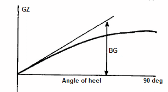
The stability criteria of a submerge submarine is BG, and the variation of the righting lever GZ with the angle of heel is as shown in the figure below.
Buoyancy and Weight Elements
A study unique to the design of submarines is the identification of the buoyancy and weight elements in a submarine. Before we do that, we will first know the meaning of each, and why they are required during the design process.
Buoyancy Elements
The components of a submarine that constitute to its total buoyancy are collectively called buoyancy elements. To identify them, let us start with the easiest one. Most of the buoyancy acts on the pressure hull (refer figure 2), and hence the entire pressure hull volume is a buoyancy element. But since the components inside the pressure hull are not in contact with sea water, they do not contribute to the buoyancy, and cannot be categorised as buoyancy elements.
The displaced volume of the outer hull (that is, the volume displaced by the steel plates of the the outer hull) also contributes to buoyancy. Note that the volume enclosed by the outer hull is not being considered here.
In some cases, the forward and aft structure that is freely flooded, may contain tanks that are not flooded. In such cases, the enclosed volume of those external tanks are considered as buoyancy elements.
The sail is freely flooded in submerged condition, and it also contains the conning tower (escape trunk), periscopes and an array of masts. The volume occupied by these structures add to the buoyancy, and hence their enclosed volumes are considered as buoyancy elements.
In the forward region, part of the torpedo tubes are within the pressure hull, and part of them are outside the pressure hull in the freely flooded region, as depicted in the figure below. The enclosed volume of the torpedo tubes in the freely flooded region acts as a buoyancy element.
The propeller shaft passes through a tube which is freely flooded, hence the volume of the portion of the propeller shaft in the freely flooded region acts as buoyancy element.
The buoyant volume occupied by all the appendages like propeller, rudders, forward fins, aft fins, sonar arrays, etc. also contribute to the buoyancy. Additionally, any air pockets created in the ballast tanks are also buoyancy elements, and hence these are unwanted as they unexpectedly increase the buoyancy on the submarine, therefore creating a positively buoyant situation.
Weight Elements
Components on a submarine that contribute to its total weight are called weight elements. All the fixed weight on the submarine as listed below are among the primary weight components:
- Pressure hull structure that includes pressure hull plating, circular stiffening frames, tanks, brackets, etc.
- Main propulsion plant that includes the diesel alternators, the electric propulsion motor (for a diesel electric submarine), shafting system, thrust block, thrust bearings, propeller, and associated machinery.
- Batteries stored in battery banks.
- Weapons stowed inside the submarine.
- Weight of all other machinery, component, and permanent fixtures on the submarine.
Apart from the fixed weight elements, there are variable weight elements, that is, their magnitudes change with time:
- Weight of crew.
- Weight of stores (e.g. fresh water, food, etc)
- Weight of consumables (diesel oil, lube oil, etc.)
- Weight of bilge, and solid waste.
- Weight of ballast.
A proper listing of all the weight and buoyancy elements are required, along with their individual weight, centre of gravity, enclosed volume, and centre of buoyancy. Once all the buoyancy elements are listed with their volumes and centre of volumes, the data is used to arrive at the total buoyancy of the submarine, and the 3D coordinates of the centre of buoyancy. Similar analysis is done for all the weight elements to arrive at the CG and weight of the submarine. This data is used to correlate the weight buoyancy relationship for a submarine.
Though this article has provided a lot of new insight on analysis of stability for submarines, there are significant parts that are related to this, but will require further knowledge to be understood. Which brings us to the next article, where we will discuss all the different types of tanks in a submarine, and their functions, and how design decisions are taken for each type of tank depending on their purpose.
You may also like to read –
- Top 12 Coolest Personal Submarines
- Pathfinder – An Underwater Submarine that Can Run on Ocean Floor
- How Do Submarines Get Oxygen?
Disclaimer :
The information contained in this website is for general information purposes only. While we endeavour to keep the information up to date and correct, we make no representations or warranties of any kind, express or implied, about the completeness, accuracy, reliability, suitability or availability with respect to the website or the information, products, services, or related graphics contained on the website for any purpose. Any reliance you place on such information is therefore strictly at your own risk.
In no event will we be liable for any loss or damage including without limitation, indirect or consequential loss or damage, or any loss or damage whatsoever arising from loss of data or profits arising out of, or in connection with, the use of this website.
Disclaimer :
The information contained in this website is for general information purposes only. While we endeavour to keep the information up to date and correct, we make no representations or warranties of any kind, express or implied, about the completeness, accuracy, reliability, suitability or availability with respect to the website or the information, products, services, or related graphics contained on the website for any purpose. Any reliance you place on such information is therefore strictly at your own risk.
Do you have info to share with us ? Suggest a correction
Related Articles
Subscribe To Our Daily Newsletter
By subscribing, you agree to our Privacy Policy and may receive occasional deal communications; you can unsubscribe anytime.


dear sir…
i am doing a seminar on stability of submerged in fluid can u give more information about it and present principle what u r using and problems encounter and solution for that
Greetings Soumya,
My interest in submarines concerns only one issue. It will take too long to explain here but I’ll happily write again later should you wish me to.
A submerged submarine is travelling at a slow but constant speed at a constant depth. There is a need to increase speed. My guess is that the engine speed can be increased quickly but the heavy submarine speed increases relatively slowly. There is an increase in thrust and torque transmitted by the engine to both the propeller and, equally but in the opposite sense, to the submarine hull. This change of torque on the hull, will cause a roll displacement, starboard up, until the gravity/buoyancy couple corrects it. If no other action is taken the crew will find themselves standing on a sloping deck temporarily. Is action taken automatically by the sail and/or aft hydroplanes, creating lift on the port side and fall on the starboard side, to correct quickly enough for the disturbance not to be noticed?
Please feel free to pass this to others.
I am working on a TSA project for my Drafting I class. The project we have tasked ourselves with is building a submarine (not a real submarine) for deep ocean exploration. Currently, I am researching submarine stability. I need permission to use the images on this site.
Where is this course being taught any way to see a syllabus for this?