

Introduction to Submarine Design
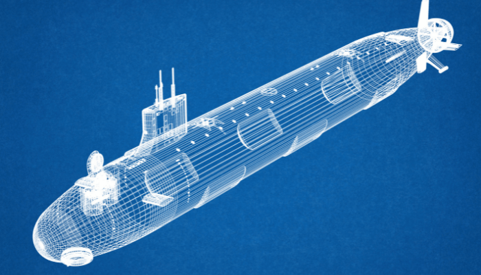
Submarines are underwater self-propelled crafts that are designed and built to perform underwater operations for a stipulated amount of time. The submarine design consists of a single or double-hull system that houses all the necessary systems and manpower required for completion of their mission.
This, though, is a very simple description of a very complex engineering product, which are used for a wide range of purposes such as underwater research, underwater rescue, and submarine warfare; the last one being the most widely used.
In this series of articles, we will study the design of naval submarines. In the first few articles of this series, we will not go into the design process, rather, we will familiarise ourselves with the design and functionalities of a submarine, its parts, general arrangement, structural design and arrangement, the stability of a submarine, the systems used in a submarine, etc.
Once we have looked into these, it would be easy for us to touch on the submarine design process. Though the design process followed by all navies is confidential and different from each other, the basics still remain the same.
The primary submarine design objectives are:
- The submarine should cater to the functional purpose of the customer.
- The design should be capable of being constructed with available resources.
- The cost of the project should be acceptable to the customer.
Parts of a Submarine
Outer Hull and Pressure Hull:
Most designs of submarines have two hulls. The hull that houses all the accommodation spaces, weapons, weapon control systems, communications and control room, battery banks, main and auxiliary machinery, is the pressure hull. It is called the pressure hull because it is designed to withstand the hydrostatic pressure at the maximum operable depth of the submarine.
The pressure hull is housed inside the outer hull, which is not pressure tight. Why? Because, in submerged condition, the spaces between the outer and the inner hull always remain flooded with seawater. Hence, the hydrostatic pressure on the outer hull is negligible.
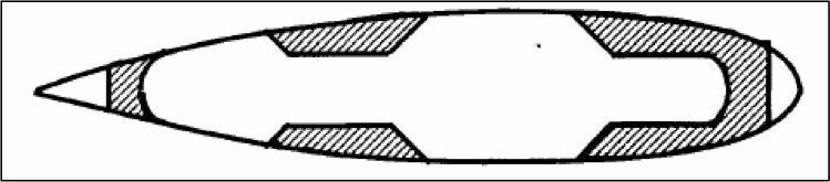
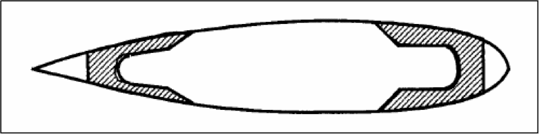
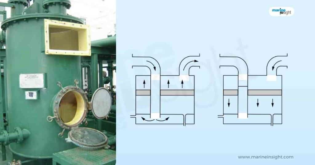
Main Ballast Tanks (MBTs):
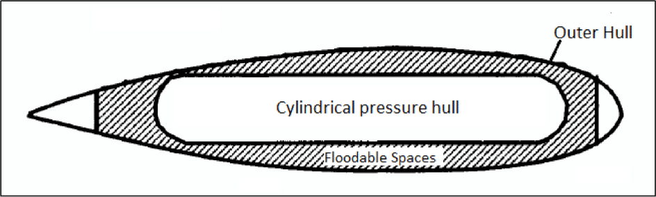
Now, the “floodable” spaces are compartmentalised into tanks, which in submarine terminology, are called Main Ballast Tanks. The distribution of main ballast tanks in a submarine depends on the shape and interaction of the outer and pressure hull.
We will understand the working of MBTs after we deal with the process of submerging a submarine, and submarine stability. Some designs have MBTs only at the forward and aft regions, and the rest of the pressure hull is flushed with the outer hull.
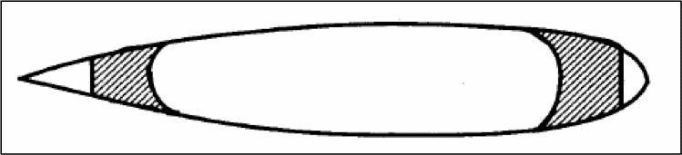
Other designs have completely different outer and pressure hull, with space for ballast between them. Some arrangements of MBTs are shown in the figures below.
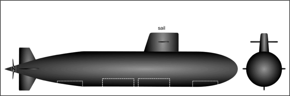
Sail or Bridge Fin:
The sail is the streamlined shaped non-pressure resistant part of the submarine over the outer hull. Its different types of masts that are deployed from within the submarine when snorkels or sails just under the free surface.
The different masts used in a submarine are periscope mast, communications mast, radar mast, weapon sensor mast, etc. These are raised from the bridge fin when the submarine requires surface monitoring in stealth mode. Figure 7 shows the sail in a submarine when the masts are not deployed.
The profile of the bridge fin in a submarine design is always an aerofoil shape, as it acts as a hydrofoil with the submarine sails with just the fin above water. This shape reduces the drag on the submarine. It is very important to keep the drag within limits as it prevents eddies and subsequently, minimises the acoustic signature of the submarine.
Control Surfaces:
When the submarine is in submerged condition, changes in direction and depth is carried out by use of hydroplanes that act as control surfaces. To understand the application of hydroplanes, we first need to know the nature of motions experienced by a submarine in submerged condition.
Unlike a surface ship, submarines are subjected to lesser heave and pitch motions due to the absence of surface wave effects. A pair of hydroplanes or fins at the forward and aft are used to control the heave and pitch independently. The hydroplanes or fins are shown in Figure 8.
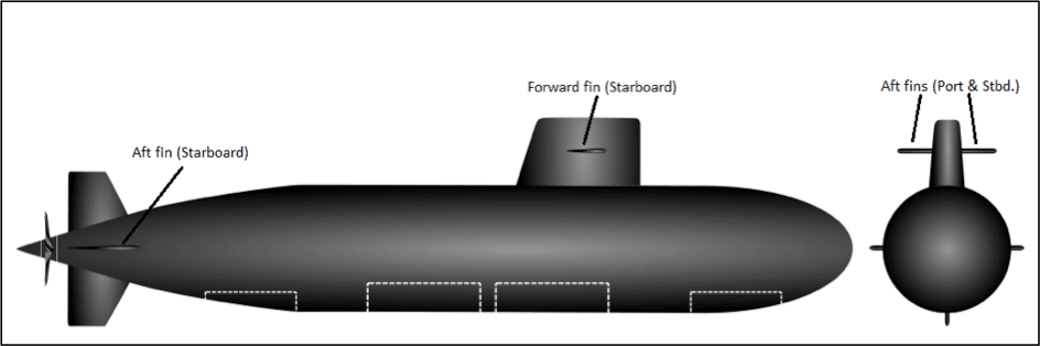
Two hydroplanes mounted at the aft in the vertical plane are used to change the lateral direction of the submarine when in motion. These are basically called rudders. Do note that unlike ships, the rudders of a submarine are forward of the propeller.
Why? Because in case of a ship, the rudder requires the propeller outflow for maximum lift efficiency. But in a submarine, since the entire hull is submerged, undisturbed streamlined flow is incident onto the rudder surface.
If the submarine rudder were placed aft of the propeller, the flow onto the rudder would be more turbulent, increasing the probability of cavitation.
One important thing to note is, hydroplanes operate at optimum efficiency only at high speeds.
General Arrangement of a Submarine
Before moving onto knowing the operation and functions of the different systems on a submarine, it is vital to know the spatial distribution of the main compartments and systems along the length and breadth of the hull. This will be best understood when referred to Figure 9.
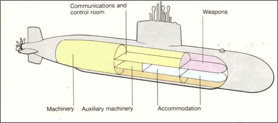
The pressure hull and outer hull are clearly distinguishable in the above figure of the submarine design. The forward part of the pressure hull houses the weapon systems and sensors. The sensors are usually housed in the flooded space between the forward of the pressure hull and the outer hull.
Sensors are always placed at the forward for reduction of noise from turbulent flow at the aft and obstruction of machinery in case of aftward position. The weapon system includes the torpedo tubes which house the torpedoes, torpedo launching system, and torpedo operating tanks.
The forward-most part of the pressure hull is used to store the weapons. They are loaded into the torpedo tubes which are located partially within in the pressure hull and extends up to the forward most periphery of the outer hull.
The midship portion of the pressure hull is used for the following purposes:
- Ship and Weapon Control Systems: All the systems on the submarine are remotely operated from the ship and weapon control centre. This compartment houses all the navigational control systems, the weapon firing systems, machinery control and monitoring panels, diving and surfacing system, steering control system, etc. All communication between the submarine crew and the naval base or any external source of data is carried out from this compartment. Submarines today are automated to such extent, that all the operations on a submarine during normal patrolling and war missions can be carried out from this compartment, with no crew required to be present anywhere outside the control room.
- Accommodation and Life Support: The accommodation modules, toilet modules, galley, cool and cold rooms are placed at the midship compartment of the pressure hull. Such positioning is not only beneficial functionally but also provides easy access to the forward and aft parts of the submarine. Since this position is also under the sail, it makes escape most feasible for the crew in emergency conditions.
- Battery bank: The source of power on a diesel submarine is hydrogen cells. These are charged by diesel alternators. Batteries comprising of hydrogen cell units are stacked in arrays and placed in a compartment called the battery bank. Usually, a submarine would have a battery bank in more than one watertight compartments for redundancy. Each battery bank has a capacity sufficient for supporting all the operations of the submarine for its endurance period. Ventilation and elimination of hydrogen from the battery compartment is a top priority, as any presence of hydrogen in the compartment may lead to explosions.
- Machinery and Auxiliary Machinery: The main and auxiliary machinery contribute to about one third the weight of the submarine. The main machinery consists of the main diesel alternators that are used to charge the batteries and its associated systems, the air conditioning plant, main high-pressure air system, etc. The auxiliary machinery compartment is separated from the main machinery compartment by a watertight bulkhead. The auxiliary or economic electric motor, auxiliary AC plant, auxiliary high-pressure air system, etc. are housed in the auxiliary machinery compartment. The diesel alternators are used to charge the batteries, which in turn power the main and auxiliary electric propulsion motors.
- Propulsion Compartment: Located at the aft of the pressure hull, this compartment houses the main electric propulsion motor, the main propulsion shaft and its associated systems, the tail shaft, and the forward and aft glands that are used to attain water-tightness at the pressure hull and outer hull openings. In the design of diesel-electric submarines, the reduction gearbox is also located in the propulsion compartment.
Hullform of a Submarine Design:
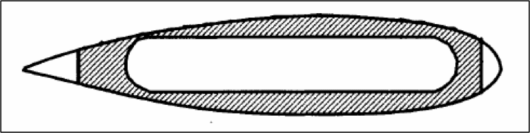
The most initial submarines used a hull form which was much different from those used in modern-day submarines. The evolution of hull form and the reasons behind it is hence an interesting aspect of submarine design. The most ideal shape of a submarine hull for minimum drag is the ideal streamlined shape with a parabolic bow and an elliptical stern, as shown in Figure 10.
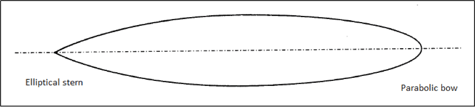
The first submarines in the 1940s used this shape for minimum power requirement and negligible flow separation around the hull. But it was observed that due to the streamline shape, the usable volume within the hull was insufficient, as the radius of the hull saw a steep decrease from just aft and forward of the midship region. This not only kept the production costs high but also weakened the possibility of incorporating multiple deck levels.
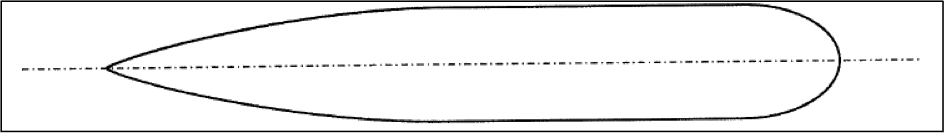
The hull form used in modern submarines (since the late 1970s) is the long cylindrical mid-body with elliptical bow and stern.
Though a shift from the ideal streamlined shape increases the drag and subsequent power requirements, the additional fuel costs over the lifetime of the submarine are offset by the low production costs, since cylindrical sections are much cheaper and easier to construct. This shape also enables the incorporation of multiple decks within the same hull volume, hence ensures more spatial use.
It is important to know that the shape and geometry of a submarine hull is an important starting point of the design since it would not only dictate the aforementioned point but also affect a range of other factors of the submarine as discussed below.
A cylindrical hull form increases the manoeuvrability of the submarine due to larger hydrodynamic forces generated by hydroplane action. It has also been observed that the minimum overall drag on the hull and best manoeuvrability characteristics are obtained for Length to Breadth ratios ranging from 6 to 8.
The diameter of the submarine is decided primarily based on the length. And the length is fixed based on the required pressure hull volume and displacement of the submarine. Multiple decks increase the usability of pressure hull volume, and the number of possible deck levels in a submarine is decided primarily by its diameter.
A submarine with one deck would have two levels within its pressure hull. Submarines with hull diameters ranging from 4 to 7 meters are restricted to one deck. It would allow two accessible levels – below deck level and above deck level, as shown in the figure below.
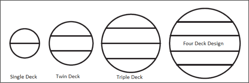
Twin decks with three accessible levels are possible in submarines with hull diameter ranging from 7 to 8 meters. Large-sized diesel-electric submarines are usually of this dimension.
Triple decks and dour deck designs are used for hull diameters ranging from 9 to 11 meters and 11 to 13 meters. Such large diameters are used mostly in nuclear-powered submarines where large vertical space is required for the nuclear power plant.
With the aspects of submarine design discussed in this article, the moot point to be extracted is that having known the parts and functions of the submarine and its systems, the art and skill of a good designer lies in trying to achieve maximum volumetric efficiency for a design.
There are some spaces within the submarine with may be highly volume-specific (for example, main ballast tanks), whereas some may have only a few specific dimensions (example, battery bank). There would also be cases where there are specific volumetric demands, but not shape specific (for example torpedo operating tanks and main ballast tanks). Depending on such demands, a good designer would prioritize the stages of design and the parameters that are fixed at each stage.
One of the most vital aspects of submarine design is its stability. Though it may seem simple as compared to ships, the understanding of submarine stability is more complex than that of a ship, as it would operate in both, surfaced and submerged conditions.
And the stability parameters of a submarine change drastically the moment a submarine dives into the water or resurfaces, which gives rise to a point where the submarine is at the tipping point of floundering. How and why is what we will discuss in the next article.
You may also like to read – Pathfinder – An Underwater Submarine that Can Run on Ocean Floor
Disclaimer: The authors’ views expressed in this article do not necessarily reflect the views of Marine Insight. Data and charts, if used, in the article have been sourced from available information and have not been authenticated by any statutory authority. The author and Marine Insight do not claim it to be accurate nor accept any responsibility for the same. The views constitute only the opinions and do not constitute any guidelines or recommendation on any course of action to be followed by the reader.
The article or images cannot be reproduced, copied, shared or used in any form without the permission of the author and Marine Insight.
Do you have info to share with us ? Suggest a correction


Latest Naval Arch Articles You Would Like:
Subscribe To Our Newsletters
By subscribing, you agree to our Privacy Policy and may receive occasional deal communications; you can unsubscribe anytime.
I like it
Moderating vessel supply growth over the next few years together with a mild improvement in the outlook for seaborne trade will enable a reduction on chronic overcapacity and so mark a recovery in the dry bulk shipping market, according to the latest edition of the Dry Bulk Forecaster, published by global shipping consultancy Drewry. Moderating vessel supply growth over the next few years together with a mild improvement in the outlook for seaborne trade will enable a reduction on chronic overcapacity and so mark a recovery in the dry bulk shipping market, according to the latest edition of the Dry Bulk Forecaster, published by global shipping consultancy Drewry.
i interest in this field like part of submarine/ship
The articles on submarine design are interesting and I would like to read some more. I am a lecturer at the maritime college Fremantle Western Australia
Hello,
Wat are the normal weaponry in military submarine. Any provision for underwater radar surveillance?
Medjor Anthon
We do not have the expertise in the submarine/defense sector.
You forgot to address one key element of your submarine design description. How will the aforementioned decks silently accommodate the expansion and contraction of the hull as the submarine changes depths (and what does this mean for equipment placement)?
How much positive buoyancy is typically built into a submarine’s design? Say it has a mass of 2000T what would it’s max buoyancy be fuelled, equipped for service but with all ballast blown?
This website has helped me learn about submarines so much thank you 😉 <3
@Donald: Glad the content is useful to you
Just watched ‘Hunter Killer ‘ and came here to know Submrine
How can I obtain permission to use information in this article as part of a university report?
@Jo: Please send us an email to info@marineinsight with your requirement.
i like it and i enjoy it because it is my fun task. i am thinking to become a submarine commander. bye
nice article.Even a layman like me could understand.Tq
@Sheeja: Glad the information provided is simple to understand ????????
A submarine driveshaft was made of epoxy and carbon fibers. Indicate two reasons why composites
have unique and excellent properties for this application? Which type of composite is more suitable for
this application? How this shaft will be manufactured? On close examination , the shaft was found to
spin irregularly and to cause vibrations. Identify four possible causes of this problem and four possible
solutions.
To whomever is interested in the field, I suggest the unsurpassed classic “Submarine Design” by Ulrich Gabler.