Designing A Ship’s Bottom Structure – A General Overview
One of the most integral parts of the ship is its bottom structure. It is designed not only to give the hull the required strength to withstand the weight of the cargo but also to withstand the external hydrostatic loads that act on the bottom of the hull.
A ship’s hull is basically made up of bent plates welded together. If these plates are not stiffened, the bending moments on the plates due to the loads may exceed the value of stress that can be withstood by the material, and hence cause failure. So, the plates are stiffened (or their section modulus is increased) by adding stiffeners to them.
Now, there are two basic ways to stiffen a ship –
- Transverse Stiffening
- Longitudinal Stiffening
Transverse Stiffening or Transverse Framing: This is carried out in ships less than 120 meters in length. In transverse stiffening, the stiffeners run along with the breadth of the ship. We would be discussing this with interesting details a little later.
Longitudinal Stiffening or Longitudinal Framing: This type of framing employs stiffeners that run longitudinally, that is along the length of the ship, and is used in all seagoing ships having a length more than 120 meters. The details would be touched upon in the later section of this article.
Now that we have an idea of the two types of framing, we need to acquaint ourselves with another categorisation of bottom structure framing in ships:
Single Bottom
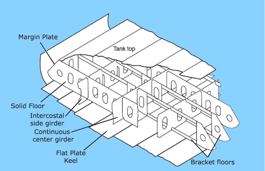
Usually, all smaller ships are single bottomed, as they do not need a double bottom to withstand the load of the cargo. In these ships, the plate floors (see the figure to understand the context of ‘Floors’ in shipbuilding) themselves act as the stiffening members of the bottom shell plating. Plate floors (as shown in the figures) constitute transversely running plates at every frame spacing.
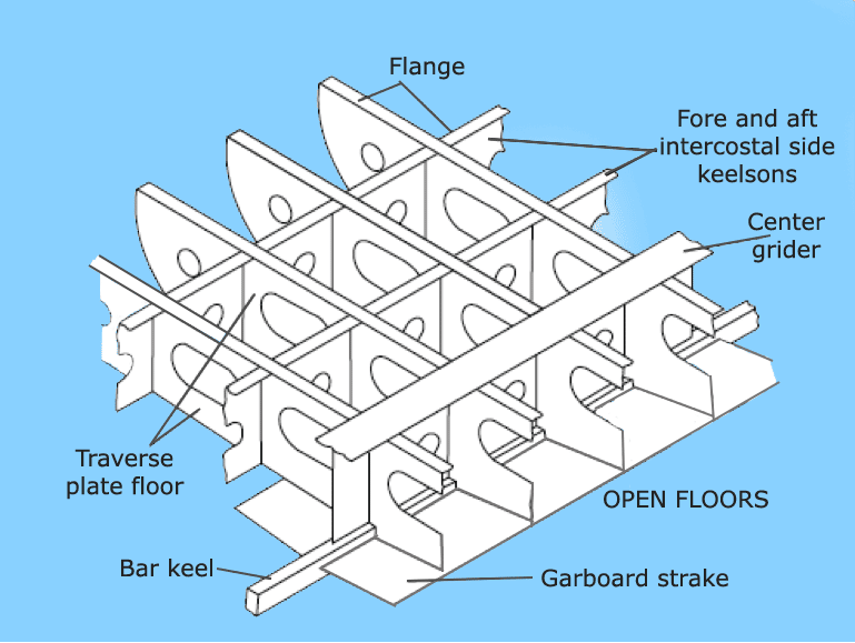
Note how the upper edge of each plate is flanged to increase the bending strength of the plate floor. Now, fall back to the basics for a while.
When the hydrostatic pressure under the bottom shell exerts a bending moment in the bottom shell, the plate floor takes up the bending stress.
So, designers treat all such members taking up bending stresses as beams. Empirically, the bending moment in a beam increases with the increasing span. So, what if we could reduce the span of the plate floor to further increase its stress capacity?
This is why intercostal girders are used (see the image). The number of intercostal girders would however increase with an increasing beam of the ship since that would also result in increased length of a plate floor.
A uniform wood ceiling is provided on top of all the plate floors, to provide stowage of cargo. But that doesn’t make it a double bottom structure as the wood would not take up any stresses exerted onto the bottom structure.
Double Bottom
All seagoing ships are double-bottomed. In such a structural arrangement, a tank top is provided above the plate and bracket floors. Bracket floors are a little different from plate floors, in as much as they are not comprised of one single plate running athwartship, but only brackets at the port and starboard end, with struts that support the tank top with the bottom shell.
Bracket floors are mostly placed at each frame, and plate floors are generally placed at every three to four frame space. The space within the double bottom (that is, between the tank top, and outer bottom shell) is used up for carrying ballast, fuel oil, dirty oil, freshwater, and other consumables.
One of the most important factors in designing a double bottom of a ship is deciding the height of the double bottom. How does a designer decide what height would be most feasible for a ship of a particular length?
This is governed by the height of the keel that is required by the ship. So while estimating the scantlings of a ship, the designer first calculates (using the rules specified by the authorised Classification Society) the height of the centre girder, which must always be housed within the double bottom. Hence, this factor now decides the double bottom height.
Double bottom heights often increase in the ways of engine rooms, as they need to take up higher stresses due to heavy machinery in those regions.
In the engine room region, all the frames are provided with plate floors, and no bracket floors are used. However, there is another factor a designer must take care of while providing an increased double bottom height in high-stress regions.
The height must not be increased abruptly, therefore resulting in a discontinuity, which would lead to concentration of stresses, and eventually a structural failure. So the increase in height should be gradually tapered up and down.
The taper should start a few frames forward of the engine room bulkhead, and continue up to three or four frames aft of the engine room to allow proper stress flow or structural continuity.
The intricacy in the design of a bottom structure begins after one has understood the above concepts. We have seen two separate categorisations of double bottoms.
The first dealt with the type of stiffening used, and the second dealt with single and double bottoms. When a ship’s bottom structure is designed, both the categories are mixed together to obtain the final structure.
Most budding naval architects initially find this part confusing, which is why let us first list down the four types of possible bottom structures:
- Transversely Framed, Single Bottom
- Transversely Framed, Double Bottom
- Longitudinally Framed, Single Bottom
- Longitudinally Framed, Double Bottom
Out of these four types, three are used, and one is not. While it is easy for experienced designers to point out that one type, it may not be easy for everyone. Because there is an underlying concept to it, which we shall understand now.
Why is longitudinal framing used when we could easily have provided transverse framing in longer ships too? The answer lies in the fact that ships longer than 120 meters are subjected to high global longitudinal bending stresses like hogging and sagging in different load conditions, unlike smaller ships.
So if longer ships would be stiffened transversely, the transverse stiffeners would have no role in taking up the longitudinal bending stresses of the hull girder, and therefore lead to more chances of failure. Hence, stiffeners are aligned longitudinally in longer ships.
It should be very clear now, that since longer ships have longitudinal stiffening, and since they are also designed to carry a higher amount of cargo, a double bottom is necessary. Hence, longitudinally framed single bottom structures (3rd in the above list) do not exist.
Since we are now done with the basics of a bottom structure, it would be easy to visualise each type henceforth.
TYPE 1: SINGLE BOTTOM, TRANSVERSELY FRAMED (Refer to the Figure 1)
- The plate floors act as transverse stiffeners, and their spans are reduced by the use of intercostal side girders that run longitudinally.
- Most single bottom ships are provided with a bar keel that extends along the length of the ship up to a certain waterline at the stem. The bar is slightly protruded outside the outer bottom shell.
- The outer bottom shell plating just adjacent to the bar keel is called Garboard strake, and its thickness is more than the thickness of the remaining bottom shell.
- All the plate floors are flanged at their tops, so as to increase their bending strength.
- Manholes are provided on the plate floors for crew access. These holes are flange too, so as to reduce stress concentration.
TYPE 2: DOUBLE BOTTOM, TRANSVERSELY FRAMED (Refer to the Figure 2)
- This is used in ships of length less than 120 meters. (See how the length factor dominates over the type of framing used)
- The bracket floors form the transverse stiffeners at every frame, and plate floors are used at every 3 to 4 frame space, or 1.8 meters intervals.
- Similar to the single bottom, to reduce the span of the plates, intercostal side girders of keelsons are used that run longitudinally. An important thing to note is that the side girders are continuous members, that is, where there is an intersection between a plate floor and a side girder, the plate floor is cut and welded on both the sides of the girder and not the other way round. Why? Remember, we needed to reduce the span of the plate floors, hence the girders will act as supporting members to the plate floors.
- Flat plate keels are used in these structures. The keel plating thickness is a very important decision-maker in the strength of the ship. This is to be calculated from the formula dedicated to this purpose, provided by the relevant classification society.
- Intercostal girders or side girders, and plate floors will have lightning holes at regular intervals to reduce the structural weight and will have manholes (flanged) to provide access.
- Drain holes will be provided on the plate floors to help drainage of liquids. Plate floors are further stiffened by flat bar stiffeners (see image below), and bracket floors, by angle struts to prevent warping.
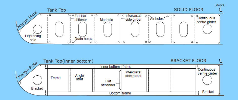
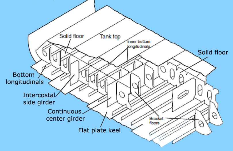
TYPE 3: DOUBLE BOTTOM, LONGITUDINALLY FRAMED (Refer to the image)
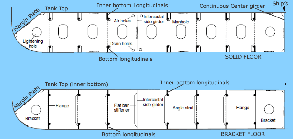
- The prime stiffening members are longitudinally running bulb sections or angle sections. The stiffeners on the bottom plating are called outer bottom longitudinals, and those that stiffen the tank top plating are called tank top longitudinals.
- The span of each longitudinal is equal to three of four frame spaces. That is, at each three or four frames, there would be a plate floor to support the longitudinal. A bracker floor is placed at almost every frame, but it does not support the longitudinals.
- Intercostal girders are used, as usual, to reduce the span of the plate floors.
- If you notice carefully, the longitudinals run across plate floors through holes called scallops. So in a frame, where it is required to support the span of a longitudinal using a plate floor, the longitudinal is welded with a small plate to the plate floor, therefore rendering the scallop as a support end.
- In bracket floors, tank top and bottom shell longitudinals are supported to each other by means of angle struts.
- In plate floors, the longitudinals of the tank top and bottom shell are supported to each other by flat bar stiffeners, to restrict bending, torsion, and buckling.
- As usual, drain holes are used for fluid drainage and air holes are used for the passage of air. Note their positions in the images, to visualise the exact layout.
- Margin plates are used in some designs, to lead the flow of waste fluids (bilge) towards the bilge wells on either side of the ship.
- A continuous centre girder runs through the length of the ship, supporting the entire bottom structure, the keel plate, and the garboard strake.
In modern analyses of the bottom structure of ships, designers take a lot of care for various modes of failure. A disastrous mode of failure other than bending is buckling, which a bottom structure can be often subjected to.
For example, consider a ship to be hogging. The outer bottom shell undergoes a compression that leads to buckling of the bottom plate and associated structure. Torsion can also be a mode of failure in cases of container ships.
So, as a ship designer, when one analyses the feasibility of a bottom structure, it is important to test for all possible modes and types of failure.
Because, for example, if a designer certifies a bottom structure only on the basis of bending stress, without taking into consideration buckling or torsion.
What could happen? In a situation, when buckling occurs, the structure might fail due to buckling (if its buckling strength is lesser than its bending strength), even when the bending stresses have not reached the failure limits!
Hence, the principal design criteria must be decided base on all possible modes of failure, at various load cases, analysed by efficient and certified FEM tools, so as to attain a safe and economical factor of safety for the structure, from all possibilities of failures at sea.
Disclaimer: The authors’ views expressed in this article do not necessarily reflect the views of Marine Insight. Data and charts, if used, in the article have been sourced from available information and have not been authenticated by any statutory authority. The author and Marine Insight do not claim it to be accurate nor accept any responsibility for the same. The views constitute only the opinions and do not constitute any guidelines or recommendations on any course of action to be followed by the reader.
Do you have info to share with us ? Suggest a correction
Latest Naval Arch Articles You Would Like:
Subscribe To Our Newsletters
By subscribing, you agree to our Privacy Policy and may receive occasional deal communications; you can unsubscribe anytime.







I am studying marine engineering l want to now about ship structure and engine and all machinery parts
Thanks ,I really appreciate joining the forum.I would want a picture of structure after the collision bulkhead resisting panting and other parts of the vessel,I will be glad ,thanks once more.
very interesting! mostly from construction point of view. Will be more comprehensive by adding some structural material as well.
I’m pursuing an unusual line of research and this was an invaluable source to me. I design fictional space vehicles, and well, felt that every craft begins with a base structure. If you’re interested in seeing more, just google “Arcos MK I” and you’re see the design I want to re-engineer to make it more realistic, within the boundaries of my own planned, of course. Any advice you might be able to offer is always welcome.
Something I noticed about the Drawing.
> “As usual, drain holes are used for fluid drainage and air holes are used for passage of air. Note their positions in the images, to visualise the exact layout.”.
The Drain holes are not touching the bottom, thus not able to drain. Maybe the air holes are a bit small.
If the Engineer decides that design allows one (or more) Manholes should be a bit larger, to accommodate a bigger person (especially if they are narrow and you must turn to squeeze through). There will always be _someone_ small enough (assuming a reasonable size) but the hole size cuts down on the choices for the Foreman during construction.
Lightening Holes big enough to pass Tools (like an Angle Grinder) through are useful.
How will the Fabricator make the plates with the air and drain holes quickly and for lowest cost. If the Engineer decides the design allows the corners should simply be Laser cut so the resulting hole size when assembled is big enough to stick the nose of a Welding Gun through (so you don’t stop/start in a corner, and have one less corner to worry about).
Think about the Machinery and Equipment available when designing internal (non-publically viewable) areas and expect that small sections are often flipped over during construction (so if the Engineer decides that the design allows there needs to be some flat spots or means to secure round portions so it is stable when it’s flipped over to do the other side).
Conveniences like those make things a bit easier to build and increase the quality of the work.
I’m not an Engineer, so if one says do not do any of that that’s OK; I just get paid more to do the work.
YT,
Rob
In which plan does the frames of the ships come?
Is it General Arrangement plan or docking plan?
@Nipun – Shell Expansion Plan
I m working on Flowing city project
It helps me to know more about design of section of the FC…!
@Shivan: ???????? Good luck with your project.
Please indicate where “bulb bars” are used in the ship’s hull.
@Sudhanshu: Bulb bars / flats are asymmetrical plate stiffeners and can be used in place of conventional stiffners.