

Loads Acting On Fore And Aft Regions Of Ships – Strengthening Against Dynamic Loading
It is worthwhile to mention that in most of the places describing the preliminary design of ship’s hull structures, utmost priority is given to the midship section, thanks to the global stresses such as maximum hull girder bending and buckling loads taken into account.
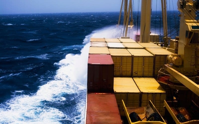
However, the fore and aft parts of the ship are not to be taken for granted as they are the critical zones subjected to local loads such as panting, pounding, green water, wave slaps, whipping, propeller-induced vibrations, just to name a few. Most of these loads are incident on the fore part, but the construction of the aft part is also equally important.
The Common Local Loads Acting On Ships
Before delving deeper into the structural arrangements prior to the requirement, let’s first go through some of the common stress problems encountered in these regions.
Panting
If you have studied ships, you would have definitely come across this term. Panting refers to the contiguous bellowing-in and bellowing-out nature of the ship’s hull plating due to variable water pressure distribution caused as a result of waves. This effect is accentuated in the forward region when the ship surges headway through. The ship bow region is the most affected area where the entire vessel encounters the wave systems for the first time. The dynamic wave pattern have variable hydrostatic pressure distribution point to point which unfortunately falls incongruous for a solid hull plate. Although, panting is still said to exist throughout the entire length of the hull, the effect dies away as the wave system at the bow starts losing its energy from the bow shoulder onwards (towards the aft).
Green Water or Wave Slap
The waves encountered by a ship on rough sea states are highly unpredictable. These giant waves can go up to tremendous heights and upon interaction with the ship’s forward, end may lash itself on to the exposed weather deck in an event marked as the wave slap/green water. However, more than the inner hull arrangements in the fore end, more concentration needs to be given in case of the deck strengthening in this case.
Pounding
This forces are induced due to the ‘Slamming’ motion of the ship triggered due to heaving or high pitching motions .This situation is further aggravated in case of empty or light ballasted conditions of ships. This intense pounding stresses incident on the plating spread over a large area extending a considerable amount of length even behind the forward collision bulkhead. Slamming can be mostly bow-flare slamming, stern slamming or bottom slamming.
Whipping
Whipping loads are a class of low cycle and high frequency stress-inducing loads caused due to slamming motions of the ship as above. But they are said to be an outcome of impact loads which are a resultant of the pounding loads.
Read : Why Do Ships Fail At Midship Region?
What are impact loads?
As the name suggests, impact loads act all of a sudden and are of large intensity in response to the natural structural response of the entire ship hull. The oncoming waves hitting the fore part of the hull, generate a large amount of impact pressure creating impact loads which in turn generate a pattern of rapid vibrations onto the material in what we call as whipping.
Impact loads also depend on the relative motion between the vessel and the water surface. Thus, pertaining to suitable design, velocity constraints and surge direction are key determinants of the net effect of impact loads.
In rough sea states, the bow of the ship performs an oscillatory motion, as mentioned in Pounding. The fore bottom floor emerges from the water and again plunges into the sea. This incessant emergence and hitting the water may spark off a vibration in the hull girder. These high-frequency vibrations cause severe loading on the entire structure and may sometimes exceed the wave-induced stress, and aggravate the situation when both are superimposed. Whipping thus is a straightforward outcome of slamming which can also induce higher girder bending moments and fatigue damage to the entire structure of the ship. Hence, it is very much wise if this is controlled beforehand at the fore region without allowing it to propagate.
Other effects due to vibrations caused by ship’s propeller and machinery aft spark off various unwanted local stresses in the stern. The fore and aft end constructions thus are needed to be taken special care of as sometimes these loads can lead to massive structural failure.
But, what are such modifications in the design?
Fore End
Now, we are in a position to understand the essence of the sound and immaculate construction of the fore end. Despite the multitude of stresses localized in this region, most of its structural arrangements have been kept in line with the chief problems of panting and pounding as these are the two most grave problems encountered in this case, proving to be the causal factors for most of the ship structural failures.
But for now, you must know the important segments comprising fore end construction and strengthening of ship structure:
- Fore Peak Tank
- Stem
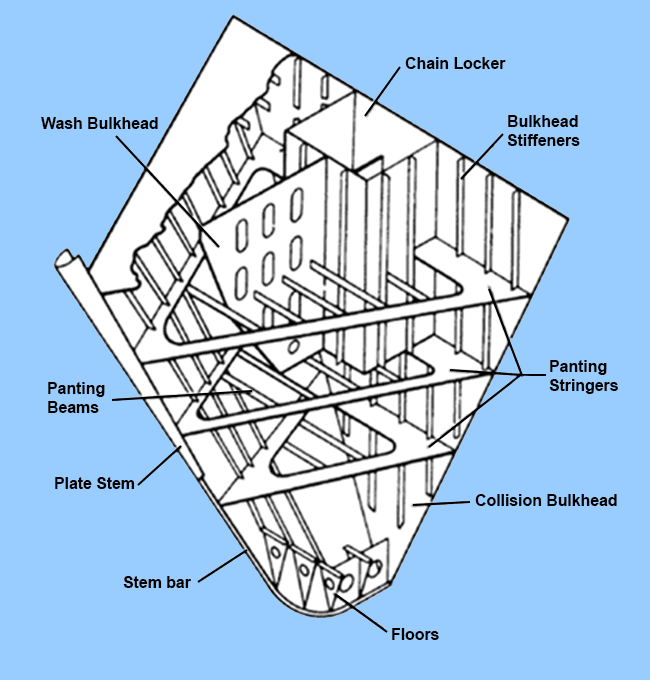
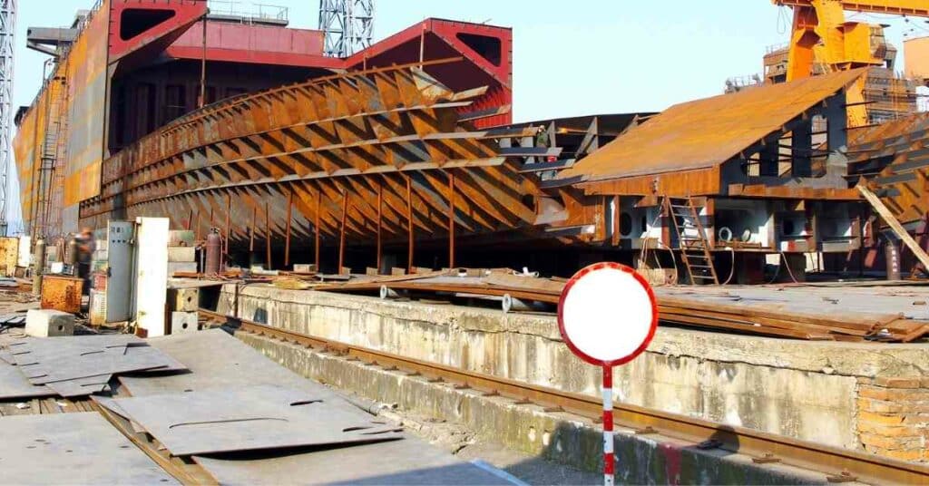
- Stiffening in the form of frames, breast hooks, wash plates, deep radius floors, pillars, panting stringers, panting beams, variety of stringers and girders. Their scantlings, material allowance and proper positioning of these strengthening arrangements dictate the “structural resilience” in light to all the localized loadings
- Chain Lockers
- Decks
- Bow (Bulbous, clipper, X-bow etc.)
Fore peak tank, as the name suggests, forms the foremost watertight tank principally used for ballasting. But more than that it serves a range of other purposes. Why?
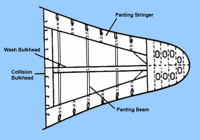
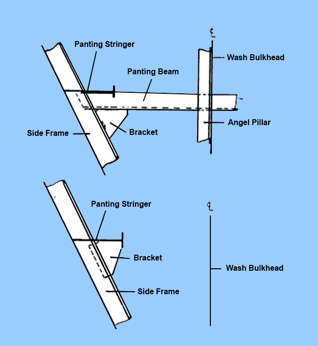
Some of the chief stiffening components include panting beams, panting stringers, angle pillars, breast hooks, perforated flats, centreline wash bulkhead. Moreover, the floors at the bottom and stringers running longitudinally along the sides at given intervals are also existent. However, an essential feature of the fore arrangement are the deviation in scantlings and positions of the net ‘Panel-stiffening’ arrangement in light of its requisite strength to sustain these load-condition vagaries.
Why? The logic is simple.
As the load parameters are more pronounced in the fore part bearing, a stake of local as well as global stresses (especially in due regard to the pressing problems of panting and pounding) are highly unpredictable, the ship designer has to pay more attention to this part to make it more “ fit”.
Furthermore, from the strength point of view, if the loading is hindered at this point, its effects on the remaining length of the ship becomes less domineering. The Classification societies for ships around the world have prepared a consensus regarding the dimensional allowance that may be purported to these plate stiffening arrangements for higher load-sustaining capacity.
What are these specially applied stiffening measures?
- Panting stringers are longitudinal stiffening members formed in a closed rounded-triangular shape (peak being the fore end) by the side stringers on both sides and the collision bulkhead at its end.
- A perforated bulkhead often exists at the centreline. Although its main function is dedicated to cargo storage and reduction of Free Surface Effects, they add to the longitudinal strength of the fore peak tank. Most of the time the angle pillars along with the panting beams are joined to the wash bulkhead. They are also very useful when the unsupported span of panting beams become large.
- Sometimes for fuller form ships like bulk carriers, the fore part is stiffened by large perforated non-watertight flats to cater to enhanced transverse strength.
- Breast hooks to stiffen the stem plate and behave as the support tip of the panting and side stringers. They also play the pivotal role of transverse strengthening of a large number of plates in the forward and side regions. However, the usability of breast hooks become pointless when there are tween decks.
Although most of the above-adopted measures are suffice to sustain high pounding loads, some extra modification are ought to be made, especially with due respect to the bottom structures.
The forward bottom plating may be subject to buckling loads due to slamming/pounding. This effect is much more adverse in winter and is the most pronounced in planning vessels that is having a higher Froude Number. Thus while designing them, the stiffening arrangements are done in accordance to the Speed-to-length relationships.
Aft End
The aft end is subject to reduced impact of local loads as compared to fore part. But still similar reinforcements are made in adjunct to the fore part. Even though the aft part is characterised by several entities such as an aft peak tank, stern frame, rudder, rudder stock, propeller and its ancillaries. However we limit our description only to the stiffening arrangements done to the stern frame in light of resisting localized forces generated in the backward region such as propeller-induced vibrations, sternward wave disturbances and to some extent, panting and pounding.
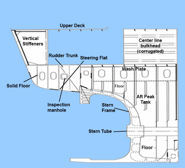
- One interesting feature of aft end stiffening arrangements is Cant beams. Cant beams are instrumental in providing longitudinal as well as transverse strength to the stern arrangement. They are radial in nature and are directly welded to the shell plating giving a kind of web frame structure. Cant beams are often coupled with cant frame providing additional strength.
- Apart from cant beams there are solid floors existent at every frame flanking the centreline girder.
- Tween decks along with the upper poop deck, if provided with adequate stiffening can bolster the longitudinal strength.
- Moreover, a set of closely running stringers join to the first main frame while the deck girders support the deck plating.
- In some vessels, panting stringers are also present at the aft peak mainly spaced within 2.5 meters according to the conventional classification rules.
- As compared to bow construction, transverse frames are more in girth and depth aft.
- One crucial point to be noted is that while there is a transom stern instead of a conventional rounded one, there is no requirement of cant beams. The transom plate while well stiffened vertically is suffice to resist local loads to a commendable extent.
Along with the rest of the ship, designers take a lot of care in designing aft and fore end constructions with adherence to panting and pounding. Sometimes, the “strength-absorbing capacity” of them are helpful in even protecting the entire ship from structural failure.
Remember Titanic? Most naval architects and experts around the globe now theoretically speculate that the ship met its misfortune only because it had damaged principally along the sides (as it had grazed past the large iceberg in an attempt to avoid it!). But instead, if judiciously it had rammed into the iceberg, the highly-strengthened fore part would have sustained maximum of the impact. Even if the fore peak tank would have flooded, still the heavy watertight collision bulkhead could have withstood the hydrostatic pressures and prevented flooding inside the rest of the ship.
Over the years, ships have suffered intense load problems in the fore and aft regions causing damage. Fortunately, modern day load predictability techniques and FEM tools have opened up many avenues for innovative, fool proof and safe designs. Most of the modern design ships have high sustainability towards abnormal local loads even in very rough sea states. More advanced strengthening measures optimized with cost have made ships safer.
Do you have info to share with us ? Suggest a correction

About Author
Subhodeep is a Naval Architecture and Ocean Engineering graduate. Interested in the intricacies of marine structures and goal-based design aspects, he is dedicated to sharing and propagation of common technical knowledge within this sector, which, at this very moment, requires a turnabout to flourish back to its old glory.


Latest Naval Arch Articles You Would Like:

Subscribe To Our Newsletters
By subscribing, you agree to our Privacy Policy and may receive occasional deal communications; you can unsubscribe anytime.
Another method for seismic retrofitting of structures is covering the damaged area with FRP materials which has gained notable acceptance from the civil engineering community in recent years. FRP composite materials possess superior mechanical properties including:
Impact resistance.
Strength.
Stiffness.
Flexibility.
Ability to loads.carry