

Flettner Rotor For Ships – Uses, History And Problems
When one thinks of a ship’s propulsion system, the conventional propeller and rudder setup is what comes to mind. While there are many other forms of powering a craft (such as waterjet propulsion, sail power etc.), a rather uncommon type of propulsion system is the Flettner rotors.
Rarely used on commercial vessels, it is an experimental concept in wind-based power generation that has been in development since the 1920s.
You can spot a Flettner rotor ship easily by the large stacks or rotors that project from the deck of the ship.
In this article, we will take a look at the rotors, the driving physical concepts, and ships that use this form of propulsion and stabilization.
What Is A Flettner Rotor?
Flettner rotors are an unconventional means of vessel propulsion and stabilization. First developed by German engineer Anton Flettner in the early 1900s, it uses a phenomenon of fluid dynamics known as the Magnus effect to propel the ship.
The thrust developed by the system and the direction is dependent on several factors and features, which are broadly categorized into:
1. Wind speed (kinetic),
2. Wind direction (directional),
3. Vessel heading (directional),
4. Rotor height and diameter (geometric), and
5. Surface properties of the rotors (dynamic and kinetic)
The driving principle is that when a cylinder is rotated about an axis, and a medium (air or water) flows past it perpendicular to the axis, then a force is generated in a direction orthogonal to both the axis and flow stream.
This force is the result of a pressure difference across the 2 halves of the rotor and is known as the “Kutta-Joukowski” force.
The concept of this force was first quantified by scientists Martin Kutta and Nikolai Joukowski who studied the case of a rotating cylinder.
Flettner rotors are used in both planes and ships, although it is still an experimental concept that hasn’t been commercially mass-produced.
The Flettner rotor is also known as the Magnus rotor. Another name for the large cylinders mounted on the deck is rotor sails or Flettner sails.
When used in the airplane industry, such aircraft are known as Flettner planes.
While the main purpose of this article is to look into the marine applications of the Flettner system, it suffices to say that planes use a rotor at the fore of the craft and ahead of the wings to generate thrust perpendicular to the ground. This thrust creates lift while the ensuing wake provides the required downwash for liftoff.
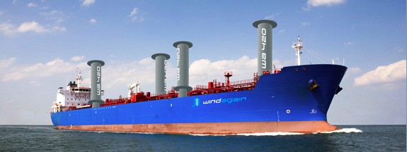
Image credit: Windagain PTE. LTD.
What is Magnus Effect?
The Magnus effect, which is the physical concept behind the Flettner rotor, was first studied by the German physicist Gustav Magnus.
He observed that a spinning body would deflect off a straight path. This deflection directly depended on the manner in which it spun.
A pressure difference between the 2 halves of the body would create a force that altered the course of the body. This pressure gradient was directly related to the geometry of the object and its kinetic properties (roughness coefficient, form factor, speed of approach, angular velocity).
This effect is most commonly studied in 3 industries- the sports field as a part of many ball sports, the defence industry where the effect could throw a guided missile off target, and in engineering applications (the Flettner rotor).
The force that is generated is known as the Kutta-Joukowski lift and plays an important role in marine hydrodynamics and naval architecture.
This is the guiding force that is utilized by Flettner rotors and certain high-speed crafts to generate lift over an airfoil (or hydrofoil).
The force generated per unit length of the body is given as:
F/L=ρvg
Here, the length L is the characteristic length of the body.
It is the diameter in case of spherical bodies, and the tip-to-tip length along with the incoming flow in case of anomalous shapes.
The main reasons that the body deviates off its original intended path are because of a phenomenon known as flow separation.
This is when the flow around a body is no longer able to stick to the surface due to certain physical alterations. In this situation, a wake (warp in the flow downstream of the body) is created.
Due to the spinning nature, this wake is formed in certain regions that create a pressure difference between opposite ends of the plane in which the ball is spinning.
The generation of the deviant force is perpendicular to both the axis of the spinning body and the direction of linear motion.
Another dynamic component that comes into play is vorticity. It is the formation of vortices behind a bluff body or spinning object.
These vortices are disturbances or turbulences created in the medium due to the spin or flow separation imparted by the body.
Vorticity is measured in terms of the strength of the vortex generation. An easy way to visualize vorticity is the whirlpool patterns created when water rushes down a sink drain.
Higher the strength, more turbulence generated and faster the water spins. The same principle is applied to the Flettner rotors.
The vorticity strength is calculated as:
G=2πωr^2
Where, r is the radius of the body (sphere or cylinder) and ω is the angular velocity (tangential velocity x radius of the body).
The most common application in engineering is the Flettner propulsion system on both airplanes and marine crafts. It is used for both propulsion and craft stabilization.
Where Are Flettner Rotors Used?
The Flettner system serves 2 main purposes on board a ship:
1. For propulsion, and
2. For stabilization
Propulsion is an integral component in marine vessels, and the more thrust that can be generated with minimum input work is always an ideal scenario. While conventional propellers are powered by marine diesel engines, the environmental damage is to be considered.
With the large number of vessels that ply the Earth’s oceans, a move to cleaner energy alternatives is preferred. One such energy source is Flettner rotors that make use of wind powers to generate thrust behind the ship.
These rotor sails are powered by small motors that are located within the hull, while the rotors themselves project vertically upwards for propulsion. As they rotate, the Magnus effect comes into play, and a horizontal thrust is generated to the aft of the vessel. The main source of energy is the motors that power the rotors, while the output is provided by the relative motion of the surrounding air.
Note, the motors alone are not sufficient due to the lower output power in a no-wind situation. For maximum efficiency from Flettner rotors, the wind must flow perpendicular to the ship’s length.
Faster the incoming wind, larger the generated thrust. For this reason, ships fitted with Flettner rotors can sail even when the wind is not in the direction of sailing. However, if the wind changes direction and approaches from the other side (port or starboard), the ship will move in reverse since the thrust is now generated towards the fore. Thus, careful analysis of the incoming wind direction must be undertaken to ensure correct heading for the vessel.
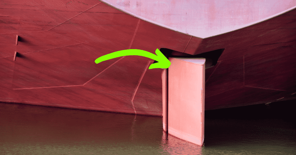
Stabilization is another function performed by Flettner rotors, although the structure orientation varies. While it projects vertically in the case of propulsion, the rotors extend laterally from the hull of the vessel for roll stabilization. Located below the waterline, they measure a few meters on each side and can be of 2 main types- active or passive stabilization.
In passive stabilization, as the vessel rolls from port to starboard, the rotors are activated, and they begin to spin. Based on the speed and direction, they can impart either a lift or downward force on the vessel.
By judging the type of force required, the roll can be stabilized by providing a righting motion using the Magnus effect. The medium in this case that provides the turbulent wake is the water flowing over the rotors.
In passive rotor stabilization, the Flettner systems on both sides of the craft rotate at the same speed in the same direction.
In the case of active stabilization, instead of having the same characteristics, the 2 halves provide different lift and down forces depending on the situation that arises.
It is incredibly precise, and if properly designed, can stabilize the vessel to a near standstill in even harsh weather conditions. However, engineering this design is complicated, and requires extensive experience.
Due to the still-experimental nature of using stabilization rotors, there are not many vessels in operation that use this system for roll stability.
History And Innovations Of The Flettner Rotor
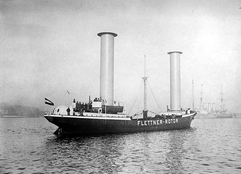
The first ship that was used to develop the concept of the Flettner rotors was the Buckau developed in Germany by the Germaniawerft. Alongside being one of the largest builders of the German U-boat submarines, it was involved in the development and testing of scientific ideas.
The team of designers that worked on the theory and oversaw the construction of the rotors were experts in the fields, and are well-known names in the aerodynamics and fluid mechanics industry.
Albert Betz (pioneered wind turbine technology), Anton Flettner (an expert aerospace engineer), Jakob Ackeret (Swiss aeronautic expert and fellow of the Royal Society), and Ludwig Prandtl (developed several mathematical and analytical models of fluid mechanics) designed the rotor vessel which was built in 1924.
The Buckau employed a twin-rotor system that measured 15 meters in height and 3 meters in diameter. The motors used to rotate the rotor sails drew 37 kilowatts of power.
Its first voyage was from Danzig (Gdansk in Poland) to Scotland in 1925, and then, later on, sailed to the Americas in 1926. However, the ship was inefficient and had difficulty in mustering sufficient power to propel the craft at an adequate speed. As a result, the project was eventually scrapped and the proposal was shelved.
Another German ship, the Barbara, was built in 1926 that attempted to use a 3-rotor system to propel the craft. Built out of Bremen by the Weser shipyard, it was also scrapped due to project delays and difficulties.
Eventually, interest renewed in the Flettner systems during the 1980s, and studies were taken up to analyze the feasibility of such a propulsion system.
Current Models And Prototype Tests
For reasons outlined in the next section, there are very few vessels with Flettner rotor systems. However, on an experimental and trial basis, there are some ships that are currently operational.
There was a proposal in 2007 to construct a fleet of 1,500 ships that would operate using Flettner rotors. Their aim was to improve cloud reflectivity by spraying seawater and creating an aerosol atmosphere above the ocean.
It was considered a novel solution to global warming and was developed jointly by Stephen Salter and John Latham. The hull design was a trimaran that could achieve a cruise speed of up to 6 knots.
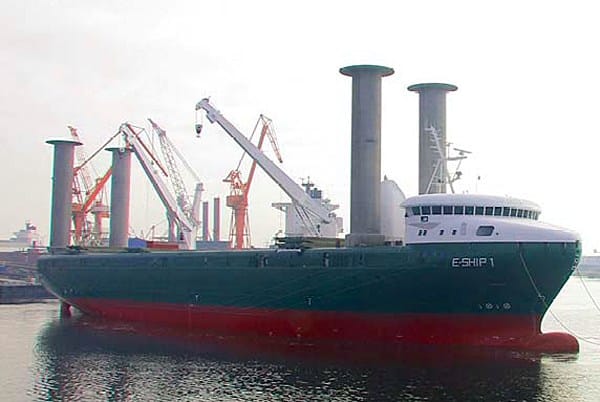
Enecron which deals in wind energy generation and technology commissioned the E-Ship-1 in 2008 that acts as an equipment and turbine transport vessel. According to the official statement from the company, it helped reduce fuel consumption by 25% compared to conventional systems.
The Viking Line company that runs ferry services in Finland and the surrounding regions commissioned STX Europe to construct a Flettner rotor powered ship in 2011. While the project was completed in 2012, the rotors were a later addition in 2018. Christened MS Viking Grace, the design was conceived by Wärtsilä in 2009.
The Norsepower company began prototyping a practical Flettner rotor system that could be installed on ocean-going vessels. The model was installed on the Maersk Pelican tanker in 2018 and is awaiting trial tests.
It utilizes a series of twin Norsepower rotors to generate cruising speeds that are said to match conventional propulsion systems.
Similarly, the MV Afros (which is a bulk carrier), has conducted tests with a 4-rotor system that has helped advance research in the design of a commercial Flettner rotor system.
For stabilization purposes, the largest vessel in use is the Eclipse, owned by Russian-Israeli billionaire Roman Abramovich, which is a private superyacht. Operational since 2011, it uses active roll stabilization and has state of the art facilities including a mini-submarine for underwater exploration.
Issues With The Flettner Rotor System
Unfortunately, Flettner rotors are not known for their efficiency, as it suffers from many types of transmission losses. A transmission loss is when total generated power is reduced due to dynamic issues that exist between where the source of propulsion is produced, and the actual propelling mechanisms.
In conventional systems, transmission losses are in the shaft vibrations and resistance faced by the propeller blades. To overcome these, streamlined blade shapes and dynamically isolated shafts are used (dynamic isolation refers to removing any connections between the shaft and surrounding media to prevent loss of energy).
However, for the Flettner rotors, the cylindrical rotors are a source of loss. Despite highly attuned designs to provide thrust in the right direction, the biggest drawback is that wind can blow from any direction, while the ship is only supposed to move at a certain heading.
For this reason, the direction of thrust varies erratically, while the propulsive power is also not constant. These are sources of inefficiency that make the Flettner system inconsistent in power generation.
Moreover, to generate sufficient power to move a large ship with the same speed as a conventional system, rotor sails exceeding 20 meters in height will need to be used. As this can also create hydrodynamic instability in the ship, it is not preferred and the height is restricted to below 15 meters.
Projections above a certain height can place excess stress on the bearings and joints that connect the rotor sails to the deck, leading to an increased chance of an accident.
So, by restricting the height of the rotors, the generated thrust is lesser than an equivalent marine diesel engine. Due to these 2 main reasons, Flettner systems are not used commonly for propulsion.
Regarding stabilization, the biggest issue is the increased beam of the vessel. Ships have a very tight range of values within which the beam can be so that it can safely dock at ports. In order to stabilize the vessel, the rotors need to extend horizontally, which creates an issue while attempting to dock.
Accidental damage to the rotor plus to the wharf are primary concerns, while there is also the risk of accidentally grazing or damaging other vessels nearby. To compound this problem, since the stabilization rotors are located below the waterline, it is near impossible to detect it from another vessel or the shore.
For this reason, Flettner rotors are rarely used for stabilization, and underwater fins are more preferred (passive and active stabilization).
You might also like to read:
- Understanding Water Jet Propulsion: Working Principle, Design And Advantages
- Propeller, Types of Propellers and Construction of Propellers
- Marine Propeller Shaft: Design And Construction
- Controllable Pitch Propeller (CPP) Vs Fixed Pitch Propeller (FPP)
- Understanding Design Of Ship Propeller
Do you have info to share with us ? Suggest a correction

About Author
Ajay Menon is a graduate of the Indian Institute of Technology, Kharagpur, with an integrated major in Ocean Engineering and Naval Architecture. Besides writing, he balances chess and works out tunes on his keyboard during his free time.


Latest Naval Arch Articles You Would Like:
Subscribe To Our Newsletters
By subscribing, you agree to our Privacy Policy and may receive occasional deal communications; you can unsubscribe anytime.
Some diagrams would have made this article easier to understand.
Thank you for your feedback