

How Do Cruise Ships Get Fresh Water?
Cruise ships are beautiful creations, outside and inside, with all their paraphernalia done to artistic perfection in an effort to woo guests. Millions of guests set sail on their dream vacations each year on these engineering and artistic marvels made to cater to their varying tastes, across different ages and nationalities.
An average-sized cruise liner carries anywhere between 2000-3000 passengers. With these many guests onboard, for several days and sometimes even months together, ever wondered how the freshwater requirement of so many people (crew included) are catered to on cruise ships?
The average freshwater consumption on these ships can vary anywhere between 500-1000 tonnes per day. It can be even higher on larger ships.
On cruise ships, fresh water is required for drinking, galleys, laundries, high-pressure washing & cleaning purposes, steam generation (distilled water), various heating & cooling systems within and outside the machinery spaces, sprinkler and hyper-mist systems for fire-fighting and recreational purposes (swimming pools & water-slides).
With this much consumption, it is imperative that cruise ships be equipped with freshwater production and storage facilities that match these requirements.
This is why they are fitted with large flash evaporators and Reverse Osmosis plants that can produce freshwater when the vessel is underway at sea and fill up the ship’s potable water tanks.
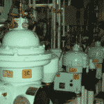
Flash Evaporators
Flash evaporators on cruise ships typically require a considerable amount of space. They have a large footprint and longitudinally extend to nearly the whole length of the compartment in which they are placed. Usually two in number, they are strategically placed close to or inside their respective engine compartments.
Now, why did I say respective engine compartments?
It is because most modern cruise liners have two separate engine compartments, viz. forward and aft engine rooms separated by a watertight bulkhead. This arrangement is given keeping in mind redundancy in case of emergency situations such as fire and flooding.
Usually, there are 4 or 5 main Diesel Generators on a passenger ship out of which 2 or 3 are placed in the forward engine compartment and the rest in the aft. In case of non-availability of one of the engine rooms, the other can be used to provide adequate propulsion power (diesel-electric) to the ship and enable it to reach port safely.
Each of these engine-rooms is self-sufficient and have their own separate air, fuel, lubrication & cooling systems. Since we are talking about evaporators specifically which use the engine jacket-cooling water, also called as HT (High Temperature) cooling water system, both sets of engines (forward and aft) have their own separate HT systems and thereby separate flash evaporators.
Their location within or near the compartment of their respective engines serves a few purposes:
1) it helps in the utilization of the maximum amount of heat of the HT water from the engines which would otherwise be considered lost if the evaporator is located farther away
2) Avoiding lengthy pipework and insulation and thereby costs
3) Less work done for the HT pump and
4) Minimize pressure losses and better circulation.
A typical flash evaporator working process is shown in the below illustration.
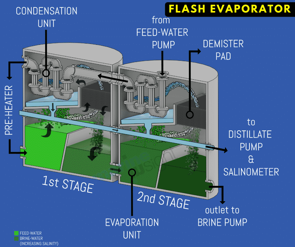
The illustration above is just for the purpose of explanation and understanding of the basic working of the flash evaporator. On passenger ships, it is common to find a multi-stage flash evaporator plant incorporating 3 or 4 stages, although here I have chosen two stages only for simplicity.
Feedwater, which is seawater, is preheated by HT jacket water from the engines to a temperature of 70-80 degrees Celsius. In many modern evaporators, this temperature can be set and adjusted to increase the production of the evaporator.
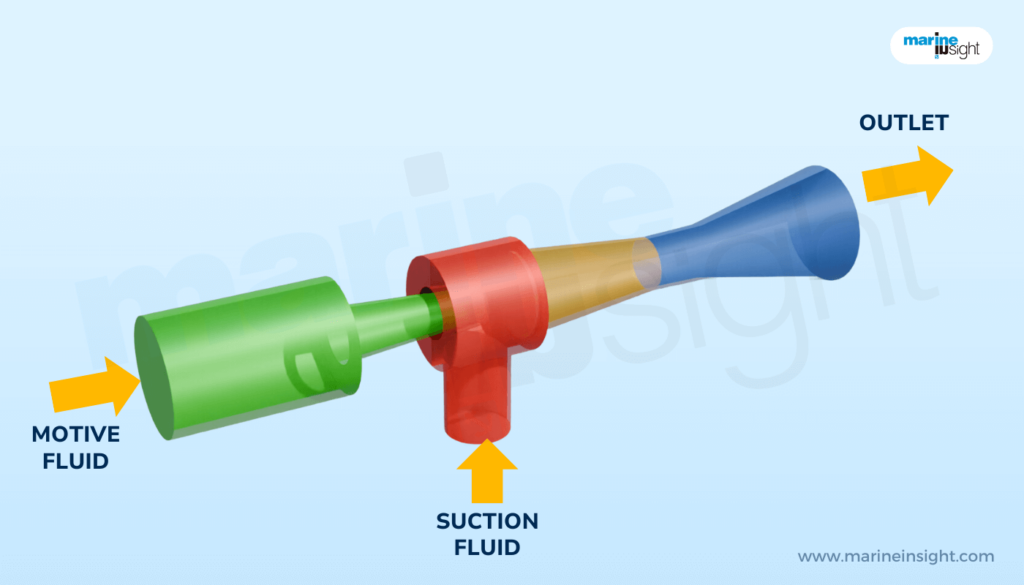
Both the flash tanks (1st and 2nd stage) are maintained under vacuum which is created with the help of the air eductor. The air eductor works on the venturi principle.
When seawater is supplied to it by the ejector pump, low pressure is created at the throat of the eductor which sucks air from the flash tanks through non-return check valves.
When feedwater at a temperature of 70-80 degrees is supplied through an orifice to the 1st stage which is under vacuum, the water immediately starts flashing off to vapour state. The flashing-off or evaporation removes the salts present in it. Any fine droplets of water present in the vapour are removed by the demister.
This vapour after passing through the demister is condensed by the seawater. Since this process of evaporation and condensation is known as distillation, the water thus condensed is called distilled water.
The seawater which is used to cool this vapour absorbs the heat from it and goes to the preheater to get further heated up by the HT jacket water, to be used as feedwater.
The unevaporated volume of water exists as brine in the first stage. This further travels to the 2nd stage flash tank where the above process repeats itself. The distillate thus collected is discharged using the distillate pump for consumption through a salinometer.
The salinometer monitors the quality of the distillate water and in case of the salinity exceeding a pre-determined value (usually above 10 PPM), dumps the water overboard by operating a 3-way valve. If and when the salinity comes down below the set value, the 3-way valve changes back to the production side.
Flash evaporators generally have a production capacity of 20-25 m3/hr depending upon seawater temperature and engine loads.
Reverse Osmosis:
Reverse Osmosis is also a common method of producing fresh water from seawater onboard cruise ships.
A typical RO plant onboard is a compact unit with a much smaller footprint than a flash evaporator. It has a capacity of 12-15 m3/hr depending upon seawater quality and the condition of the filters.
A cruise ship can have one or two RO plants, depending upon the requirement. A typical RO plant found onboard cruise ships is shown below.
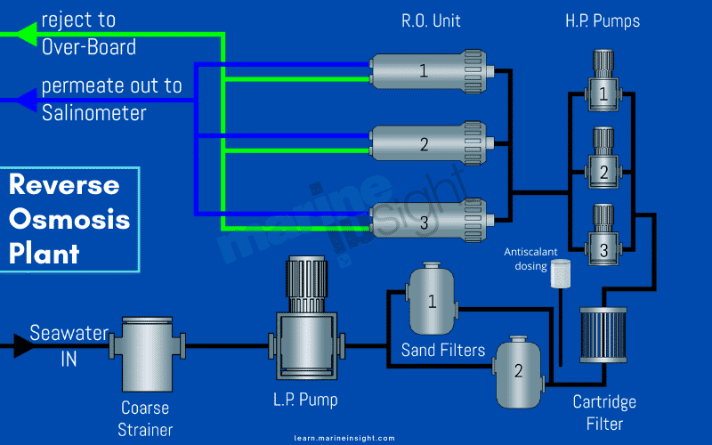
Seawater is supplied by a low-pressure feed pump through a coarse strainer. This coarse strainer separates medium-sized impurities such as mud, some shells etc that might have escaped past the sea-suction strainers.
From here the seawater is further filtered by the sand filters, which are usually two in number. They are effective in the removal of solid particles and micro-organisms from the water. Sand filters themselves require backwashing by either seawater or fresh water at least once a day when the plant is operational or before shutdown. This is to ensure continued plant efficiency.
After the sand filters, the water is dosed/treated with an antiscalant chemical. As the name suggests, this is to prevent/inhibit scale-formation on the RO membrane surfaces which can result in fouling and loss of plant efficiency.
Thereafter, the water undergoes fine filtration in the cartridge filter. This is a 5–10-micron filter which separates finer impurities before the water reaches the membranes. The cartridge filter is replaced according to differential pressure which is when it exceeds 1 bar.
The filtered water is now supplied to the membranes by the High-Pressure pumps which are usually 3 or 4 in number. The HP pumps operate at a pressure of 50-70 bar and aid in the final step of the RO process, the separation of dissolved salts during the passage through the membranes.
The membranes consist of 3-4 banks. Each bank has a set of membranes, one of which is a primary which receives water from the HP pumps as feed and produces clean freshwater as permeate and reject which is a solution of the separated salts from the feed.
The clean permeate goes out from the plant as produced freshwater whereas the reject goes to the secondary membrane as feed where it again splits up to permeate and reject. The permeate produced joins the clean permeate outlet whereas the final stage reject goes overboard.

Like the distilled water from the evaporator, the water produced thus can be used as technical water although, for use as boiler feedwater, specifically water from the evaporator is preferred because of lower conductivity.
However, the water produced onboard from the evaporator as well as the RO plant is unfit for direct consumption being devoid of any minerals and taste. For this, the water requires further treatments.
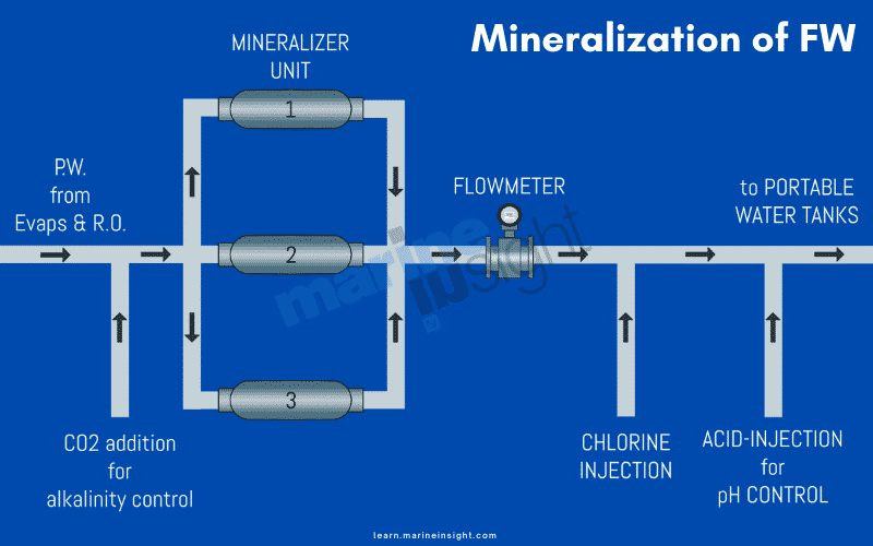
For consumption purposes as potable water, this water is passed through mineralizers, treated with carbon dioxide and chlorinated for disinfection.
The mineralizers are usually 2 or 3 in number and are filled with granules of minerals such as calcite which lend taste, pH and some hardness to the water. This is the reason why mineralizers are also known as re-hardeners. The alkalinity and hardness aid in providing anti-corrosive properties to the water and also make it safe and fit for consumption.
In most modern cruise liners, carbon dioxide is added to the production water for re-mineralization and control of pH.
The pH of potable water has to be maintained below 7.8 (the ideal range is between 7.2 and 7.6).
The re-mineralization process can increase the pH to a high level thus preventing the dissolution of calcite minerals. Therefore, CO2 addition becomes necessary to bring down the pH within control limits.
When CO2 is added to water carbonic acid (H2CO3) is formed. This serves the following purposes: 1) It helps in the dissolution of calcite in the water. 2) It helps in lending bicarbonate alkalinity to the water as carbonic acid exists in water as hydrogen ions and bicarbonate ions. 3) It helps in the control of pH.
The mineralized freshwater is now treated with chlorine. The chlorine is dosed with the help of metered pumps which operate automatically and are calibrated to maintain the free chlorine concentration around 2.50 mg/L(PPM).
It is to be noted that as per the standards of the United States Public Health (USPH), the free chlorine concentration should reach 2 PPM within the first half an hour of the start of production to potable water and should at all times be maintained between 2-2.50 PPM. This is to be ensured by manual tests at least once every 4 hours by the watchkeepers.
On some ships, particularly older vessels, acid dosing is used for pH control. In this method, Sulphuric acid or Hydrochloric acid is pumped using a metered pump in auto mode with the pH setting adjusted to maintain pH between 7.2-7.6.
Post mineralization, chlorination and pH treatment, the water goes to the potable water tanks for storage. The tanks are usually filled in pairs with ship stability in consideration.
Consumption is taken from the tanks filled first and the most recently filled tanks are used last to allow the chlorine to settle. The residual free chlorine content of the stored water of each unused tank has to be checked by the watchkeepers before putting the tank to use.
The water for consumption too must be chlorinated as per USPH standards such that a minimum concentration of 0.2 PPM is maintained at all times at the highest deck of the ship.
Most cruise lines though, strive to maintain at least 1-1.50 PPM at all times at the highest deck, super ceding USPH standards, to ensure that they are always in compliance.
Related Reading: How Are Cruise Ships Powered?
Potable water bunkering
Despite having two evaporators and a similar number of RO plants with large production capacities, the quantity of potable water onboard often poses a challenge as the demand almost always tends to match or exceed the supply of potable water onboard cruise ships.
The main reason for this is that the ships spend quite a large amount of time at ports. An average cruise liner operating in say, the US-Caribbean route can have as many as 5 port days in a week. A cruise ship could be docked for an average of 8-10 hours, which can at times even go up to 12 hours.
This automatically means that these ships get very less time at sea. This is also considering the time the ship is on manoeuvring and near coastal waters where it cannot produce potable water due to the lack of depth and the possible presence of shore-based impurities in the water.
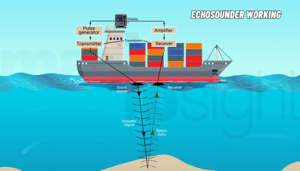
The ship has to wait to reach at least 4 nm from the shore to be able to start the evaporators and that too once started can only be used to fill the technical water tanks until the ship reaches deeper and cleaner seas where it is safe to change over the production to the potable water tanks.
The RO plants too, should ideally only be started at a minimum depth of 50 meters to avoid any risks with respect to fouling of the filters and worse, any damage to the very sensitive membranes.
For the above reasons, it is normal for cruise ships to bunker potable water weekly or as per demand. The bunker is normally undertaken at the home port or the turnaround port of the vessel where the ship bids goodbye to one set of guests and welcomes another.
The bunker water is usually supplied by a tanker or terminal. As per USPH guidelines, the potable water supply should be checked for quality before supplying to the vessel and a written declaration must be provided to the ship mentioning the Chlorine content and pH.
Also, the bunker flanges and pipelines should be well covered and protected during and after bunkering to prevent impurities and contamination. The lines must only be used for potable water and not for any other purpose.
The potable water hoses from the shore terminal or water tankers are connected to the ship’s potable water bunker manifold. The line further from the bunker station to the potable water tanks has two line filters which require cleaning and sanitization after every bunker.
When bunker commences these filters need to be de-aerated thoroughly and it is to be ensured that there are no leaks in way of these filters. The water has to be chlorinated and pH adjusted before filling the PW tanks.
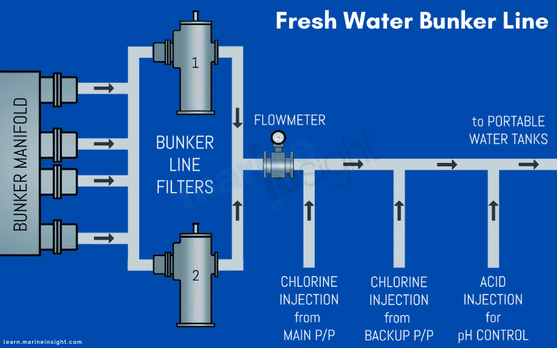
Just like production water from evaporators and RO, the bunker water too needs to attain a minimum of 2 mg/L (2 PPM) of free chlorine content within the first 30 minutes of the commencement of bunkering and thereafter maintain a value of 2-2.50 PPM at all times during the bunker. This is recorded in a bunker chlorination chart recorder.
Since the flow rate of bunkering can be quite high, roughly 250-300 m3/h, one pump isn’t usually sufficient for chlorination and therefore two pumps are used.
The chlorine and acid need to be topped up as required. This is the responsibility of the watchkeeping team. They also need to make manual tests for chlorine content and pH every hour during bunkering to make sure that the water is getting chlorinated as per USPH standards.
The chlorination for production water, distribution water, far point (highest deck) and bunker are recorded and monitored with the help of circular charts which need to be replaced every 24 hours or as per requirement.
Thus, we discussed how ships produce freshwater, both technical water for machinery uses as well as potable water from the evaporators and reverse-osmosis plants as well as mineralization and chlorination processes of such potable water. We also discussed the potable water bunkering procedure.
You might also like to read:
- Watch: How The World’s Largest Cruise Ships Handle All The Waste?
- Top 10 Most Expensive Cruise Ships in 2021
- Video: Why Are Cruise Ships White?
- Video: Are Large Cruise Ships Safe?
- Watch: Where Did All Empty Cruise Ships Go Amidst COVID-19 Pandemic?
- How Much Fuel Does a Cruise Ship Use?
Disclaimer :
The information contained in this website is for general information purposes only. While we endeavour to keep the information up to date and correct, we make no representations or warranties of any kind, express or implied, about the completeness, accuracy, reliability, suitability or availability with respect to the website or the information, products, services, or related graphics contained on the website for any purpose. Any reliance you place on such information is therefore strictly at your own risk.
In no event will we be liable for any loss or damage including without limitation, indirect or consequential loss or damage, or any loss or damage whatsoever arising from loss of data or profits arising out of, or in connection with, the use of this website.
Do you have info to share with us ? Suggest a correction
Disclaimer :
The information contained in this website is for general information purposes only. While we endeavour to keep the information up to date and correct, we make no representations or warranties of any kind, express or implied, about the completeness, accuracy, reliability, suitability or availability with respect to the website or the information, products, services, or related graphics contained on the website for any purpose. Any reliance you place on such information is therefore strictly at your own risk.
In no event will we be liable for any loss or damage including without limitation, indirect or consequential loss or damage, or any loss or damage whatsoever arising from loss of data or profits arising out of, or in connection with, the use of this website.
Latest Marine Technology Articles You Would Like:
- 10 Harmful Effects Of Impure Air On Ship’s Machinery

- 10 Important Things to Check While Starting Fuel Oil Purifier on Ships
- 10 Noteworthy LNG-Powered Vessels
- 10 Points for Efficient Turbocharger Operation On Ships
- 10 Practical Tips to Handle Engine Room Pumps
- 10 Precautions to Take Before Operating Controllable Pitch Propeller (CPP) on Ships


Subscribe To Our Newsletters
By subscribing, you agree to our Privacy Policy and may receive occasional deal communications; you can unsubscribe anytime.