

Design And Construction Of Ice Class Ships – Part 2
This article is the second part of the article series “Design and Construction of Ice Class Ships – Part 1“.
Design Philosophy Of Ice Capable Ships
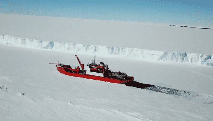
Beginning this last section of our series, we delve into the design considerations of an ice-capable ship. Now an obvious question arises is that is there differences in design amongst icebreakers, ice-going and ice-class ships? The answer is, yes.
However, to put it simply, the best way to avoid the confusion is to hierarch these three in the sense that an icebreaker requires most of the ice-breaking capabilities, as they are dedicated to the function of breaking ice and often escorting other vessels in ice-clad waters, followed by ice-going and ice-class, as described in the previous article .
Ice-class/ice-strengthened vessels have a significant difference between icebreakers and ice-going as they are general-purpose ships with capabilities to tread in icy water conditions with an escort like an icebreaker, remember? So they lack several functional and design capabilities of the other two. We briefly summarize ice-class ships in our last and concluding section as they do not have huge intricacies in their hull form.
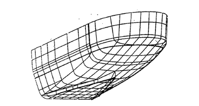
Reiterating back from our previous article, the hull form design of an ice-capable ship takes into consideration parametric angles in terms of stem angle, flare and waterline entrance angles.
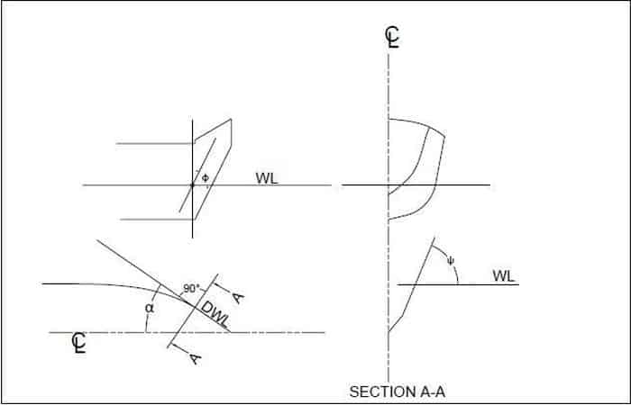
Figure 7: Essential Ship angles
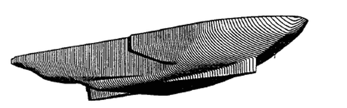
The hull form of ice-going ships including icebreakers has always been a debated topic. Over the years, the hull form has undergone several evolutions, transitions and developments to enhance icebreaking and negotiating performance without compromising propulsive efficiency.
Discussing the history of all those developments is time-consuming and may be referred to in trusted resources if required. But the crux of designing a suitable hull form for ice ships lies in the aim for reducing the overall ice resistance while effectively breaking and clearing ice.
As we know, ice resistance due to crushing is several times higher than due to bending by shear loads. So, the main aim is to reduce this ‘crushing’ resistance as much as we can. Also, the open-water resistance (mostly frictional) is also not compromised. So over the years, from experience and theoretical analysis, the hull form of ice vessels form various countries have evolved significantly in different countries.
Factors affecting the design of ice-capable ships are as follows:
- Ship’s beam
- Ship angles
- Hull condition
- Ice condition
- Velocity
- Service of the vessel
Ice has a varied response against various kinds of failure modes like crushing, bending and buckling during interaction with the ship. So, the hull form is made firstly to negotiate the ice loads effectively and secondly, the hull is strengthened to counter the ice loads response during various conditions of loading without structural failure.
Estimation of ice loads is a very challenging task. These depend on various complex and uncertain factors like ice distribution, type of ice, the motion of ice and in fact, the overall, ship-ice interaction process itself. Ice loads affect both the hull locally, affecting local structures and inducing high-pressure localized ‘point’ or ‘concentrated’ loads whereas global loads affect the hull structure as a whole. Modern-day simulations have enhanced the scope of computing plausible loads enacting on the hull girder as well as the local zones of the ship throughout. Sometimes, small-scale model experiments also help. But the foolproof strengthening of the hull materialistically and structurally is important, but not sufficient. The accurate creation of the hull form is also equally important.
One simple thing is that response to resistance must not be confused with loads, though both are intricately related. If the problem of resistance can be solved, that does not mean the problem of oncoming loads is solved and vice versa. Selection of suitable material and strengthening means improves response to loads up to a certain extent.
At the end of the day, the complete hull form decides the effective response of the hull to loads as well as resistance. Achieving an ideal design with maximum effectiveness is difficult to achieve. However, data on past designs have made designers informed about the pros and cons of a particular design, making room for improvisation or recreation.
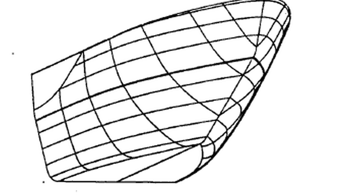
First and foremost, the bow of the ship is of great concern as it cuts or rams through the ice, disintegrates it and clears it to make a channel for ice transition. So, it goes without saying that in most of the modern designs the prow of the ship if of a sharp-edge ‘V-form’ to enhance cutting through ice.
As breaking the ice by shear to create low-value shear resistance is of main importance, the Stem Angle is made as low as possible as it has been seen that a high stem angle increases crushing resistance which can increase the total ice resistance. A sharp rake, i.e. a shallow stem angle is found to pronounce the vertical component of the enacting ice load by creating a lift of the vessel causing large bending moments amounting to the desired shear resistance more significant over high modulus crushing resistance. Though no hard and fast rules exist for the stem angle to cater for maximum ice clearing efficiency, an angle of 15-20 degrees has proved to yield desired results.
The width of the hull in the forward area is also a crucial factor. As it goes without saying the maximum beam of the vessel should occur near the forward unlike the midship areas in other general-purpose ships. This is to ensure that the ice slabs affront get broken more easily and end up fast aft near the propeller wash, an important phenomenon for reducing ice resistance.
However, care should be taken to avoid buff forms of the hull in the bow region as this can hinder effective breakage of large ice and at the same time also increase resistance. It has been formulated that the ice resistance of ships chiefly depends on ice thickness, vessel speed and beam.
A good design would sharp V-shaped brow with a broad beam close to the bow. In this manner, the Longitudinal Centre of Gravity (LCG) should be well forward of the midship as it will create a narrow tapering typical aft body making the chances of ice accumulation pretty less, also helping clear ice in the downwash.
Also, the lines forward of midship should be less fair to enhance clearance of ice and avoiding clinginess to the hull. So, in this manner, the salvaged ice floes end up in the propeller wash or get laterally “pushed” aside from making a channel. Two classic examples are the spoon-shaped bow and the square-shaped bow, also known as the Thyssen-Was bow. These two have proved to be highly successful in mitigating ice with lesser resistance. They have superseded the previously existing hull form of wedge-shaped bow, which had not proved to be very efficient.
The bulbous bow is generally avoided as it has been found to increase ice resistance. Furthermore, since in icy waters, there is a lesser occurrence of waves and the forward speed of the vessel is in nominal limits, wave resistance is not a problem, thus making a bulbous bow absolutely redundant, if not burdening.
Square and spoon-shaped bows can increase the shear force for breakage and cause lesser resistance. A circular bow has also been shown to be effective but can cause a problem of slamming problems.
In modern bow designs of ice-capable ships, the wide beam in the forward region rapidly tapering to the bow has been a successful trend, but this can cause a small problem of hull elongation to make up for its deadweight capacity. Lengthy hulls, on the other hand, can pose problems in turning and lateral movement in ice.
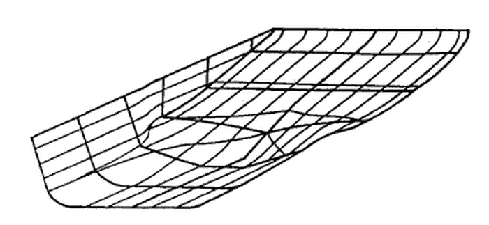
The stern of efficiently proven vessels can be envisaged to be sharp, steep and narrow for good seakeeping and icebreaking properties. A stern is often kept very high with more than ample propeller clearance to cater for lesser accumulation or ‘clinging’ of ice in it’s after wash and enhance the creation of a better channel in case of dedicated icebreakers. Ice-capable ships like breakers and ice-strengthened ones are characterised by the rapid collapse of frames to better deal with broken-off ice by either pushing it aside from the channel or plunge it down towards the propeller wash.
Another interesting feature of ice-capable ships is the presence of reamers, both near bow and stern. Reamers are merge points of a bow and middle body in the forward and stern and middle body at the aft. They are like sharp knuckles which act as obtrusion to ice wedges, pushing them aside the channel underneath the ice wall boundaries.
Stern reamers also similarly break ice aft of midbody and push the ice underneath the channels when operating astern. Regarding waterlines, the half-angle of the entrance is desired to be kept in the same order as the rake/stem angle as the fineness of the waterline is said to produce large downward forces required for bending, thus shearing. Block Coefficients are variable, mainly dependent on the bow and stern forms and the capacity, but is tried to be kept low.
Midship section coefficients may vary but can be kept high owing to seakeeping, stability purposes and often to compensate the lesser available volume in the forward and aft regions owing to its typical hull form. The flare of these ships has always been a debatable topic.
European designers had postulated over the years that a small flare angle would be congenial in lifting the vessels desired for breaking the ice by bending whereas Canadians had argued that a large angle would be equally opportune. No concrete judgement is available. However, proven assertions from U.S Coast Guard and several latest Russian designs have vouched for a minimum 10-20 degrees flare.
Another common technology in modern icebreakers is the presence of bow and stern propellers which help in the clearing, disintegrating and washing off of ice also facilitating proper flow of broken ice in its downwash.
A Brief Introduction To Ice Class
Needless to say that all ice-plying vessels are governed by a different set of classification rules dictating their make, building materials, design, arrangement, structure, functionality, equipment, stability, machinery, safety, etc.
All vessels like icebreakers, ice-strengthened ships and other ice-going vessels are all encompassed under Ice Classification Rules. However, as discussed above simply ‘Ice-Class’ ships are any other general-purpose ships with ice-strengthening and some modification in equipment and operationality to sustain in cold icy waters, with a necessary escort like an ice-breaker in moderate to heavy ice conditions. They have no dramatic changes in hull form design.
Several (but not all) classification societies have their own set of rules under the name Polar Class (PC) which deals with the capabilities of all these ships qualifies to ply in icy waters. Also, a set of exclusive generalized regulations have been adopted by the IMO namely, the ‘International Code of Ships Operating in Polar Waters ‘.
The foremost classification widely followed by more or less all classification societies is the segregation of vessels based on serviceability. They are descended from PC 1-7 based on the service of the vessel, the ice conditions and most importantly, the timing of operations.
| PC 1 | Year-round operation in all polar waters |
| PC 2 | Year-round operation in moderate multi-year ice conditions |
| PC 3 | Year-round operation in second-year ice, which may include multi-year ice inclusions |
| PC 4 | Year-round operation in thick first-year ice, which may include old ice inclusions |
| PC 5 | Year-round operation in medium first-year ice, which may include old ice inclusions |
| PC 6 | Summer/autumn operation in medium first-year ice, which may include old ice inclusions |
| PC 7 | Summer/autumn operation in thin first-year ice, which may include old ice inclusions. |
Also, classification societies like DNV-GL have their own set of classification as also do another set of rules called Finnish-Swedish Ice Class Rules. For example, as per DNV rules:
- Ice Class 1A*: Highest class notation alluding to ships operating in all ice conditions, from extreme to moderate, without icebreaker assistance. Obviously, this includes ice-going and icebreakers and definitely not simple ice-strengthened/ice-class ships.
- Ice Class 1A: Capable of trodding in difficult ice conditions, with icebreaker escort.
- Ice Class 1B: Moderate ice conditions with an icebreaker.
- Ice Class 1C: Light ice conditions, with icebreakers. Mostly, cargo ships capable of lying in very cold regions.
Also, IMO’s ‘International Code of Ships Operating in Polar Waters ‘ also have their own categorization, viz., Category A, B, C. We do not delve into the details of each and every aspects of classification. But a crucial aspect of classification is the material selection and strengthening.
Needless to say, ice-class vessels are given extra care in terms of strengthening and material selection to sustain in their operation. An ice-class defines a region in ship’s hull where maximum plausible ice loads can occur and names it as ‘Ice Belt’. This demarcation helps in identifying the zone of maximum plausible loads from ice.
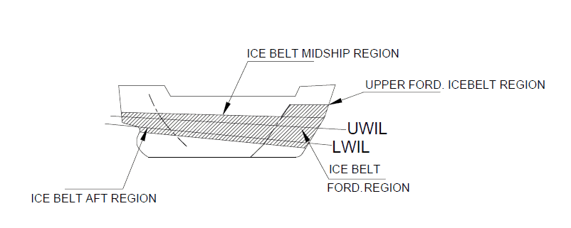
The ice belt is flanked by the Upper Ice Water Line (UWIL) and Lower Ice Water Line (LWIL). The ice belt region is given extra care by the classification guidelines in terms of more strength, scantling and stiffening arrangements. UWIL and LWIL are the upper and the lower limit of the waterlines in icy waters, respectively which are used to estimate the feasible zones of ice loading in ships.
So, in all ice-capable ships, the materials used in the ice belt is high breed high tensile steel of various grades like AH, DH, EH. Other areas can be either high tensile steel or mild steel (B, D, E, F etc.) of varying scantlings as per requirement. The details of all such rules and regulations are available in classification documents.
Obviously, the Ice Belt is different in icebreakers and ice-going ships as compared to simple ice class. It goes without saying that in prone areas, the stiffening and framing arrangements are specially decided based on the vulnerability of oncoming ice loads, where the stiffening members like ice stringers etc. may have high scantlings and closely spaced.
Corrosion and abrasion protection are also given as per classification guidelines as the hull shell plating is highly vulnerable to corrosion, freezing, embrittlement and abrasion in frigid conditions.
This brings us to the end of our tri-article, long discussion on ice ships. Hope you have gained some information. Over to you…
Do you have info to share with us ? Suggest a correction

About Author
Subhodeep is a Naval Architecture and Ocean Engineering graduate. Interested in the intricacies of marine structures and goal-based design aspects, he is dedicated to sharing and propagation of common technical knowledge within this sector, which, at this very moment, requires a turnabout to flourish back to its old glory.


Latest Naval Arch Articles You Would Like:
Subscribe To Our Newsletters
By subscribing, you agree to our Privacy Policy and may receive occasional deal communications; you can unsubscribe anytime.