

What Is Fatigue In Ships?
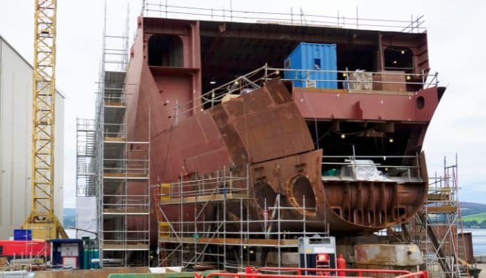
Before a vessel is constructed, it is required to be analytically checked from various perspectives from a structural point of view.
This is to numerically validate the vessel design and check for discrepancies or shortfalls that may lead to structural failures, losses, weak links, or non-compliances in varying scales. By varying scales, all such things may be localised to a single small-scale region or maybe on a global level that can compromise the vessel structure as a whole or to large extent of damage.
Hence, for every ship, there needs to be an analysis done to check for structural sanctity and identify and assess the associated risks from the ship design.
Earlier, most analyses were done from first principles and numerical techniques. However, with the advancement of time, all forms of analysis are now finite element-based and further integrated into computational methods executed through software resources.
The types of structural analysis primarily performed on vessels are:
- Direct Strength Analysis
- Free and forced vibration analysis
- Ultimate Hull Girder analysis
- Fatigue Analysis
Direct strength and ultimate hull girder analysis mainly deal with the structural analysis of the vessel and its components on global and local levels.
Free and forced vibration analysis deals with the structural response regarding vibrational modes under the given lightweight, deadweight, machinery and equipment operations, and external loading at global and local levels.
What is fatigue in ships?
Just like living beings, non-living beings also get tired after a certain point in time!
Fatigue means the structural effects on a body due to repetitive or cyclic loading. In other simple words, fatigue loads stem from the ‘wear and tear’ or ‘weariness’ of a material over a period of time.
In physical terms, the effects of fatigue loads start from cracks or deformities on the body or object due to the applied cyclic loads.
When further continued to be impressed upon by the loading, the problem further aggravates and finally culminates into a gross failure of the structure or member.
So, in another sense, fatigue loads can also be defined as the time-variant long-term loads that add up over time and influence the strength-bearing capacity of a material, manifesting in failures.
Unlike other loads, they are not short-term and do not immediately affect the structure. It is the slowest form of loading effect, contrary to impact loads that lead to structural failures in the shortest span of time(within a few seconds).
For all practical purposes, the influence of the cyclic or repetitive loads on a structure can lead to failure in a period ranging from a few months to a few years.
As a simplified example, if you consider a machinery part, like a bearing of a car or bike engine or gear, it is suffering a repeated amount of loading over its period of usage, also depending on the intensity.
At one point in time, after maybe ten or fifteen years, depending on your usage or maintenance, you will face a complete breakdown of your vehicle beyond any form of affordable repair.
Again, if you live in a rainy place, and your window pane breaks, a temporary makeshift arrangement would only stay for a few days or months, and you need to look for a much for stable arrangement. All these are simple instances of fatigue loading.
As time is the main factor in fatigue loading, from a fatigue point of view, for a structure, it is important to see ‘how long the structure or body survives’. In technical terms, this is known as fatigue life. So, for the above examples, the 10 or 15 or 20 years for a vehicle, or the few months or days for the temporary window pane, is nothing but the fatigue life.
Unlike other forms of structural analysis, there is no direct or proven way of exactly estimating the failure point of the structure.
Unlike a direct strength analysis, where the exact level of stresses can be predicted for a structure failure or vibrational analysis and the exact modes for local and global-level deformations and resonance values can be captured under the given conditions, it is not feasible to say for sure after how long a structure can fail under fatigue loading.
Again, going back to the above example, if you buy a car today and use it regularly, it will break down beyond repair on a specific date in 2035 or 2040. It can be more; it may be less; it can be somewhere within your expected longevity.
Process of fatigue analysis

Fatigue failure of an overall structure occurs due to the concentration of local stresses that initiate deformity/discontinuity or crack growth and propagation over a span of time and some number of stress cycles.
In a physical sense, the methods for fatigue failure can be summed up in the following broad steps:
- Crack initiation is the starting point of crack or creak formation. Initially, it begins at a microscopic level and increases significantly with time and load cycles applied over the period.
- Localised stress concentration at places of crack(often measured as amplified stresses due to the structural break and measured in terms of stress concentration factor during analysis purposes).
- Crack propagation: the spreading of crack from one place to another due to further applied loads.
- Global stresses are due to the culmination of these localised time-variant stresses and lead to fatigue failure on a global level.
Hence, for fatigue analysis, one can just predict or approximate the fatigue life. And thanks to numerical methods, we have developed ways to at least roughly predict the fatigue life of a structure under given conditions of loading and usage. For all practical purposes, the fatigue life of a material can be deduced approximately out of the following methods:
- Stress-life method
- Strain-life method
- Crack growth method
- Probabilistic methods
We do not go into the complex details of the above and just briefly touch upon them. However, it is fair to know that the stress-life and strain-life methods are the simplistic methods used classically and are based on first principles.
Stress-life methods involve numerical and physical techniques where a specific S-N curve is derived from experimental material testing.
Here, S stands for maximum stresses applied to the material, and N stands for the total number of cycles to failure. Hence, to know the average life or number of cycles to failure, the maximum feasible stresses applied for the material are identified.
The corresponding N value for that coordinate gives the desired outcome. As obvious, the curve has an inverse proportionality (logarithmically decreasing in nature); that is, the lower the applied range of stresses, the higher the fatigue life.
Mathematically, there is another simplified relationship that expresses fatigue life in terms of time or fatigue years. This is called Miner’s formulation and is expressed as the number of cycles at a defined stress level (n) divided by the total number of cycles to failure (N). This is based on a combination of mechanical and statistical formulations.
Strain-life method is similar to stress-life but uses strain as a quantitative parameter instead of stress. This is commonly used for materials that do not exhibit elastic properties, and thus, stress values are not correctly measurable or exact.
The crack-growth method employs a direct physical relationship between the material and the corresponding fatigue life by analysing the crack growth or, in other words, the extent of crack formation and increment of a selected region under the influence of a stress or load cycle. Details of this methodology are beyond our scope of discussion.
Probabilistic methods are based on empirical relationships using techniques for probability estimations and statistical data.
Fatigue analysis in ships
Fatigue analysis in ships is carried out mainly using the simplistic methods discussed above and sometimes probabilistic ways based on past data of similar vessels.
All classification guidelines mandate fatigue analysis as a crucial part of structural analyses and specify guidelines and empirical relationships as a part of the ‘Fatigue Damage Analysis’ problem statement. The S-N curve or Miner’s formula often acts as a guiding principle for the processes.
Here, essentially, as a common practice, some specific frames are chosen from the ship and fatigue analysis is carried out using only the longitudinal members, that is, deep members/primary members and secondary members like stiffeners, that mainly contribute to the longitudinal hull girder strength of the vessel.
It is redundant to choose other frames as some critical frames often showcase the ‘fatigue fitness of the whole vessel’.
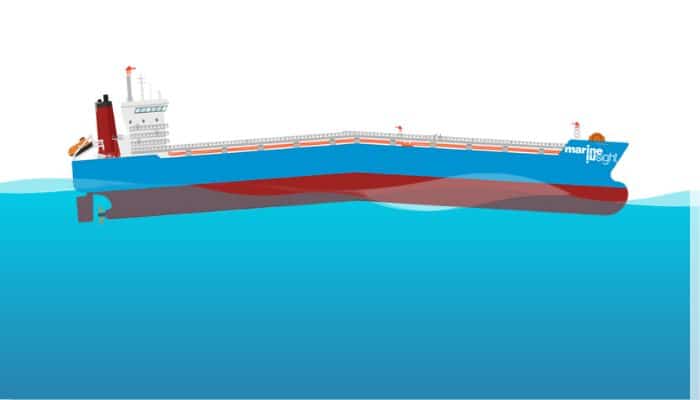
As the middle region of any vessel is the most susceptible region to bending moments, the midship region is inevitably chosen. Other frames are often chosen in the forward and aft regions as deemed suitable.
For longer ships, the number of frames is often increased to analyse a better picture. For the fatigue strength of a vessel, the following factors play a vital role:
- Material for stiffeners
- Scantlings of stiffening members
- Span of a member: This is the unstiffened length of a longitudinal member. (Usually taken as the distance between frames, bulkheads, and other deep members).
- Welding used
- Associated plate characteristics
- Orientation and arrangement of strengthening members and structure as a whole (stiffener spacing, etc.)
- Any form of structural discontinuities (if any)
As a rule, the fatigue life of all the relevant members is checked against a benchmark criterion that may depend on the ship type, size, utilities, and a variety of other factors.
However, for all practical purposes, the benchmark for fatigue life set for a ship structure is an average of 25 to 30 years. This value may exceed this and have a maximum of 30+ years or even 35 for large and expensive ships. Again, this value maybe even something like 15-20 years for smaller vessels or river vessels.
Often the analysis is carried out for worst-case scenarios. For instance, for a chosen frame, if the next frame or bulkhead is more faraway in its forward than at the aft, the span for a longitudinal stiffener is usually chosen as the distance between the given frame and the forward bulkhead or frame that is the maximum distance.
For non-compliance against the pre-set criteria for even a structural member, there is rework in design, like changing the scantlings or increasing the stiffening arrangement. For example, if a stiffener shows a fatigue life of 25 years against a benchmark requirement of 30, the scantlings are altered prior to construction, or its longitudinal span is changed.
Nowadays, instead of manual calculations, dedicated software and tools are often used for fatigue analysis using inputs like scantlings, span, stiffener spacings, and so on.
You might also like to read-
- Understanding Vessel’s Hull Speed And Its Determination
- Understanding Turning Circle Of A Ship
- What Is The Pivot Point Of A Vessel?
- What is Automatic Identification System (AIS)- Types And Working (FAQs)
- 7 Best Handheld Marine GPS in 2022
Do you have info to share with us ? Suggest a correction

About Author
Subhodeep is a Naval Architecture and Ocean Engineering graduate. Interested in the intricacies of marine structures and goal-based design aspects, he is dedicated to sharing and propagation of common technical knowledge within this sector, which, at this very moment, requires a turnabout to flourish back to its old glory.


Latest Naval Arch Articles You Would Like:


Subscribe To Our Newsletters
By subscribing, you agree to our Privacy Policy and may receive occasional deal communications; you can unsubscribe anytime.