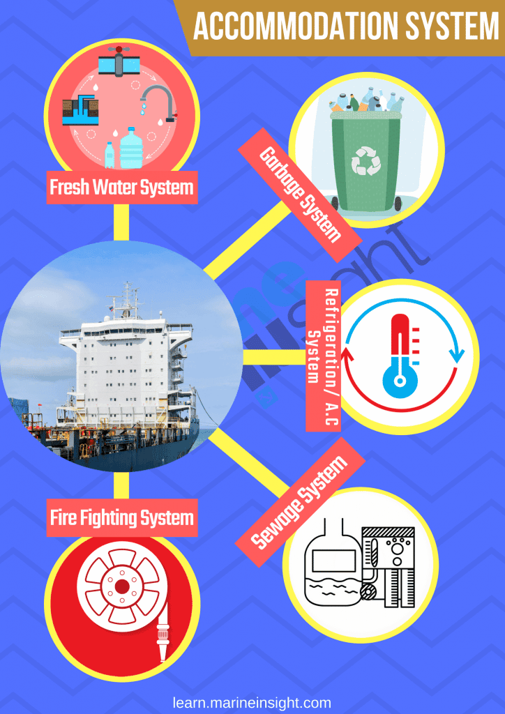
Systems For Accommodation Area Of A Ship You Must Know About
Accommodation of a ship is the living space where cabins for ship’s crew are located, along with galley, provision stores & refrigeration, messrooms, recreational rooms, gymnasium, meeting rooms, lockers, etc.
The accommodation area is supported by water supply, sewage system, air condition system, fire safeties, etc. These systems are very different as compared to the conventional ones found in residential buildings on the land.
In this article, we will take a look at all important systems for the accommodation areas of a ship:
Domestic Fresh Water System
Freshwater in the domestic freshwater system onboard may be taken from shore or produced onboard. The freshwater generator produces water for use in the domestic freshwater system on the ship.
This distilled water produced by freshwater generator passes through a mineraliser (hardening filter) to reduce acidity and increase the mineral content of the water before directed to one of the freshwater storage tanks.
If distilled water is required directly is for boilers, the mineraliser is bypassed.
A silver ion steriliser is supplied to destroy bacteria and leave silver ions in the stored water, providing effective sterilisation whilst the water is stored.
Normally one domestic freshwater FW tank is in use, with the second being filled or ready for use, as standby.
Steriliser
Steriliser onboard can mainly be of two types – silver ion steriliser or ultraviolet steriliser.
The silver ion steriliser is operated to treat water already in the freshwater storage tank. The hydrophore unit draws water from one of the freshwater storage tanks and passes it through the steriliser unit.
The water then passes between the electrodes and silver ions are introduced, producing a concentrated sterilising solution. This solution is then introduced into the selected freshwater storage tank as required.
The concentration is such that when diluted, the residual level of the silver ions in the tank remains toxic to the bacteria. If the water remains in the tank for an extended time, it may become necessary to retreat and restore the required ion balance.
Note: Samples of the water in the storage tanks, the supply system and the steriliser should be taken and analysed at regular intervals, as recommended by the manufacturer.
The ultraviolet sterilizer is a device that carries out the sterilization of water instantaneously by using ultraviolet rays. Accordingly, it does not have a remaining effect like that of chlorine sterilization. It consists of a quartz tube, a germicidal lamp and a water filter.
The germicidal lamp emits ultraviolet rays to kill the germs in the water. Never see the germicidal lamp with naked eyes, since the powerful ultraviolet rays can be harmful.
Related Read: Important Points Seafarers Must Consider For Clean Drinking Water System On Ships
Mineraliser
Mineraliser or rehardening filter is designed to treat distilled water from the freshwater generator, producing water that is more suitable for human consumption.
Mineraliser consists of dolomite stones. As the water passes through the mineraliser, acidic components are neutralised by reaction with calcium and magnesium salts in the dolomite, resulting in an improved pH, this should be between 7.5 and 10 (This can be adjusted by increasing or reducing the quantity of dolomite in the filter).
A part of the dolomite is dissolved in the water, supplying necessary mineral salts and hardness. Domestic freshwater for general use is stored in two freshwater tanks, ports and starboard.
There are generally two freshwater hydrophore pumps (one running and other standby), which draw from the freshwater tanks and delivers to the hydrophore pressure tank, which is provided with an air cushion, topped-up from the working air system.
The pressure in the hydrophore tank controls the starting and stopping of the hydrophore pumps. As the water is consumed, the tank pressure drops, which automatically starts the selected pump and refills the tank.
When the pressure increases to a predetermined value, the pump will automatically stop. One pump is normally in use, with the second pump shutdown or ready for use.
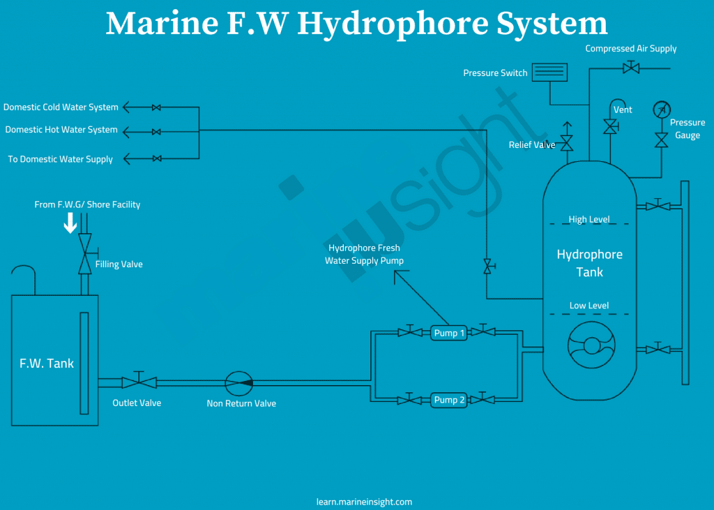
From the hydrophore tank the water flows into three systems:
Domestic cold-water system and accommodation services
This system covers the water supply to drinking water fountains and the accommodation for use in cabins, pantries and the galley.
Domestic hot water system
This system supplies continuous hot water to the accommodation for domestic purposes. Water is circulated continuously by the hot water circulating pump, passing through a calorifier, where it is heated by either steam or electrically to the correct temperature.
Topping-up of the system is from the hydrophore tank. This arrangement of constant water circulation ensures that hot water is available at an outlet immediately as a tap is opened and reducing waste due to cold water flowing until hot water is available.
Related Read: 10 Ways To Reduce Freshwater Consumption On Ships
Engine room and deck service system
This system supplies to deck freshwater hose connections, engine room freshwater hose connections, and many other places in the engine room where freshwater is required, for e.g. filling connection for expansion tank, filling connection for chemical dosing tanks, generator turbocharger water washing connection, stern tube seal unit, bilge oily water separator and so on.
Domestic Refrigeration System
There are three refrigerated chambers where all the provision food is stored, namely vegetable room, meat room and fish room.
The refrigeration plant is automatic in operation and consists of two reciprocating type compressors, two condensers with an evaporator coil/fan unit in each of the three refrigerated chambers (meat, fish and vegetable rooms).
Cooling for the meat, fish and vegetable rooms is provided by a direct expansion R134a system. Liquid R134a refrigerant is passed to the evaporator coil for the room and the expansion valve regulates the amount of liquid flowing to the evaporator in accordance with the gas outlet temperature; if the temperature has risen, more refrigerant passes to the evaporator.
The liquid expands to the gas stage in the evaporator coil by extracting heat from the air in the refrigerated chamber. The air in the cold chamber is circulated over the evaporator coils by an electrically-driven fan.
The supply of refrigerant to the expansion valve is regulated by means of a temperature-controlled solenoid valve in the supply line.
The refrigerated room evaporator is equipped with a timer-controlled electric defrosting element. The frequency of defrosting is chosen by means of a timed defrosting relay built into the starter panel.
Under normal conditions, one compressor/condenser unit is in operation, with the other ready for manual start-up, with all valves shut until required.
The system is not designed for parallel operation of the compressor units and the valve on the compressor unit, which is out of service, must be fully closed.
The compressor draws R134a vapour from the cold chamber evaporators and pumps it under pressure to the condenser where it is cooled by water circulating from the central cooling FW system.
The gas is condensed under pressure into a liquid. The compressors are protected by high pressure, low pressure, low lubricating oil pressure, and condenser cooling water failure cut-out switches.
The liquid refrigerant passes through a filter/dryer to the cold room evaporators.
Thermostats in each chamber enable temperature controllers to operate the solenoid valves independently so as to reduce the frequency of compressor starts and running time.
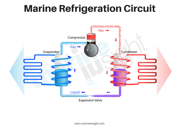
The evaporators accept the refrigerant as a super-cooled vapour from the expansion valves. The opening of the expansion valve is regulated by the refrigerant gas temperature at the outlet from the evaporator.
This vapour extracts heat as it passes through the evaporator but is still colder than the liquid stage. The cold vapour then returns to the compressor, passing through the heat exchanger where it cools the liquid refrigerant further.
The solenoid valves at the air coolers (evaporator units) are opened and closed by the room thermostats, allowing refrigerant gas to flow to the evaporator when open. With the solenoid valves closed, no gas flows to the evaporators and so no gas flows back to the compressor suction. The low-pressure switch will stop the operating compressor.
Any leaks of refrigerant gas from the system will result in the system becoming under-charged. The symptoms of the system under-charged will be low suction and discharge pressures with the system eventually becoming ineffective. Bubbles will appear in the liquid-gas flow sight glass.
Related Read: 8 Most Common Problems Found in Ship’s Refrigeration System
When required, the additional refrigerant can be added through the charging line, after first venting the connection between the refrigerant bottle and the charging connection in order to prevent any air or moisture in the connection pipe from entering the system.
The added refrigerant is dried before entering the system. Any trace of moisture in the refrigerant system will lead to problems with the thermostatic expansion valve icing-up and subsequent blockage.
The meat and fish room operating temperatures are -20°C and the vegetable room operating temperature is +4°C. The temperatures in the chambers are regulated by means of the room thermostats which activate the associated solenoid valve supplying gas to the air cooler/evaporator.
Accommodation Air Conditioning System
The air is supplied to the accommodation by an Air Handling Unit (AHU) located in the air conditioning unit room. The AHU consists of an electrically-driven fan drawing air through the following sections from the inlet to the outlet:
• One air filter
• One steam preheating unit
• One enthalpy exchanger
• One reheat section
• Two air cooler evaporator coils
• A humidifier section
• A water eliminator section
• A fan section
• A discharge section
Humidification of the air is arranged with automatic control and this is fitted at the outlet section of the AHU.
The air is supplied through the distribution trunking to the accommodation. Cooling is provided by a direct expansion R134a system.
The plant is automatic and consists of two compressor/condenser units supplying the evaporators contained in the accommodation air handling unit. The expansion valves for the coils are fed with liquid refrigerant from the air conditioning compressor, the refrigerant having been compressed in the compressor, then cooled in the condenser where it is condensed to a liquid.
The liquid R134a is then fed, via the filter dryer, to the evaporator coils where it expands under the control of the expansion valves, before being returned to the compressor as a gas. The phase change (liquid to gas) takes place in the evaporator coils where it extracts heat from the air passing over the outside of the coils.
Related Read: Learn About Fatal Bacteria that Grow in Ship’s Air-Con System
The compressors are fitted with an internal oil pressure activated unloading mechanism which affords automatic starting and variable capacity control of 100%, 75%, 50% and 25% of full capacity by unloading groups of cylinders.
This variable capacity control allows the compressor to remain running even when the load is relatively light and thus avoids the need for frequent stopping and starting.
The compressor is protected by high and low-pressure cut-out switches, a low lubricating oil pressure trip, a cooling water pressure trip, and high pressure and oil supply pressure differential trip.
A crankcase heater is provided for use when the compressor is not running.
Related Read: What are the Safety Devices on the Refrigeration System of a Ship?
Any leakage of refrigerant gas from the system will result in the system becoming under-charged. The symptoms of the system being under-charged will be low suction and discharge pressure and the system will eventually become ineffective.
A side effect of the low refrigerant gas charge is apparent low oil level in the sump. A low charge level will result in excess oil being entrapped in the circulating refrigerant gas, causing the level in the sump to drop.
When the system is charged to full capacity, this excess oil will be separated out and returned to the sump. During operation, the level as shown in the condenser level gauge will drop.
If the system does become under-charged, the whole system pipework should be checked for leakage. The only reason for an under-charge condition after operating previously with a full charge is that refrigerant is leaking from the system.
When required, additional gas can be added through the charging line, after first venting the connection between the gas bottle and the charging connection. The added refrigerant is dried before entering the system.
Any trace of moisture in the refrigerant will lead to problems with the thermostatic expansion valve icing-up and subsequent blockage. Cooling water for the condenser is supplied from the low-temperature central freshwater cooling system.
Air is circulated through ducting to outlets in the cabins and public rooms. The airflow through the outlets can be controlled at the individual outlets.
Sewage Treatment Plant
Sewage (black water) from the accommodation spaces is drawn by gravity or by vacuum through the pipe system to the ejector on the sewage collection tank.
The vacuum in the system is maintained by circulating fluid from the collection tank through the ejector. The sewage in the collection tank is discharged to the sewage treatment plant located in the engine room.
A sewage treatment plant is a biological unit which works on the aerobic activated sludge principle. The plant will treat black and grey water and is fully automatic in operation.
Air is supplied to the sewage treatment unit by an independent aeration blower. This sewage treatment plant consists of a tank with four main compartments:
Bioreactor with matrix (aeration compartment)
The sewage in this compartment is from the lavatory pans, urinals and hospital in the accommodation spaces. The incoming effluent material passes through a screen to prevent the passage of inorganic solids into the bioreactor compartment, where it mixes with the activated sludge already present.
The passage through the vacuum system breaks down the raw sewage into small particles which mix easily and encourage bacterial action.
The matrix unit in the compartment ensures movement of the effluent and rapid biological breakdown of the raw sewage by the bacteria present. Air is supplied by means of a blower and distributed evenly through the tank by aerators.
The gas produced during the bacterial action which takes place is vented to atmosphere at the funnel top. Oxygen from the air is essential for the aerobic activity of the bacteria.
These organisms require oxygen for digesting the raw sewage and it also assists by agitation and mixing the incoming sewage with the water, sewage sludge and bacteria already present in the compartment.
Settling or clarification compartment
Effluent from the bioreactor compartment flows to the sedimentation tank compartment where sludge is separated by gravity.
The sludge is then returned to the bioreactor compartment screen section by means of an airlift supplied with compressed air from the aeration blower.
The effluent then passes into the bottom of the filter tank.
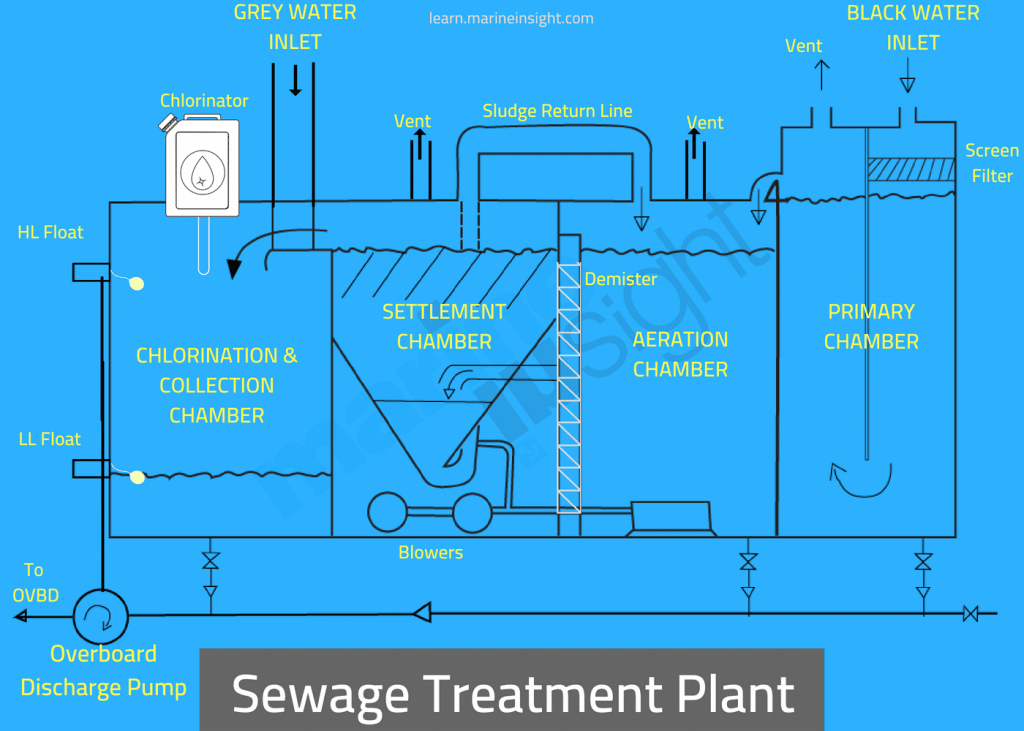
Filter compartment
The activated carbon filter in this chamber breaks down any remaining micro-organisms and filters out any solid material.
Air is supplied by means of the blower and distributed evenly through the tank by the aerators at the bottom.
The filter requires backflushing with steam every month. The clean effluent flows from the filter compartment into the sterilisation compartment.
Clean water sterilisation or discharge compartment
This compartment is provided with float operated switches which activate the discharge pump when the high level is reached and stop the pump when the compartment is nearly empty.
Sterilisation of the treated effluent is chlorination with sodium hypochlorite by means of a chemical injection pump or by manually adding chlorine tablets.
The sewage treatment plant works automatically once it is set, but periodic attention is required, and the unit must be monitored for correct operation.
The treatment plant discharge pump may be set to discharge overboard, into the double bottom sewage collecting tank or to the port and starboard deck connections for discharge to shore. The sewage collecting tank is either pumped in the same manner.
Related Read: MARPOL ANNEX 4 Explained: How to Prevent Pollution from Sewage at Sea
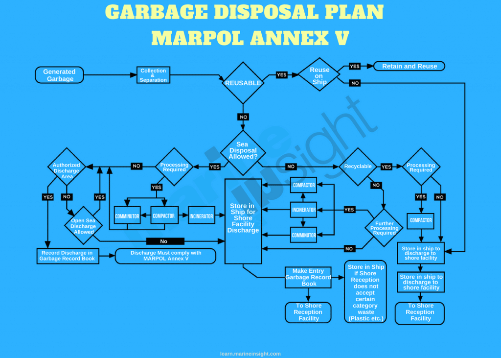
Garbage Disposal System
Annex V of MARPOL 73/78, the Regulations for the Prevention of Pollution by Garbage from Ships, controls the way in which waste material is treated onboard ships.
The regulations require the vessel to have a Garbage Management Plan in place. The plan should outline the procedures for handling, segregation, storage and subsequent disposal of the vessel’s generated garbage.
The plan is to be clearly displayed in locations used for the handling of waste and name the person on board responsible for the plan management.
Although it is permissible to discharge a wide variety of garbage at sea, preference should be given to disposal utilising shore facilities where available. A summary of the garbage disposal regulations is given next.
The special areas are as follows:
• The Mediterranean Sea.
• The Baltic Sea.
• The Black Sea.
• The Red Sea.
• The Persian Gulf.
• North-West European Waters.
• The Gulf of Aden.
• The Antarctic.
• The Wider Caribbean Area.
Food waste ONLY is permitted to be disposed of inside a special area, but not less than 12 miles offshore.
Every ship has to have a standard Garbage Management Plan which outlines the responsibilities of crew members and the location of all the garbage bins and collection area.
Related Read: Marine Pollution by Ships -Tips for Reducing & Recycling Waste at Sea
Fire Fighting In Accommodation
At various places including inside each cabin, smoke detectors are present to detect smoke from the fire. Each deck consists of portable fire extinguishers DCP type usually two in number, one port side, and one starboard side.
Fire hydrants and fire hose are present outside on the deck wings on each deck. Galley has a separate fire extinguishing system of its own.
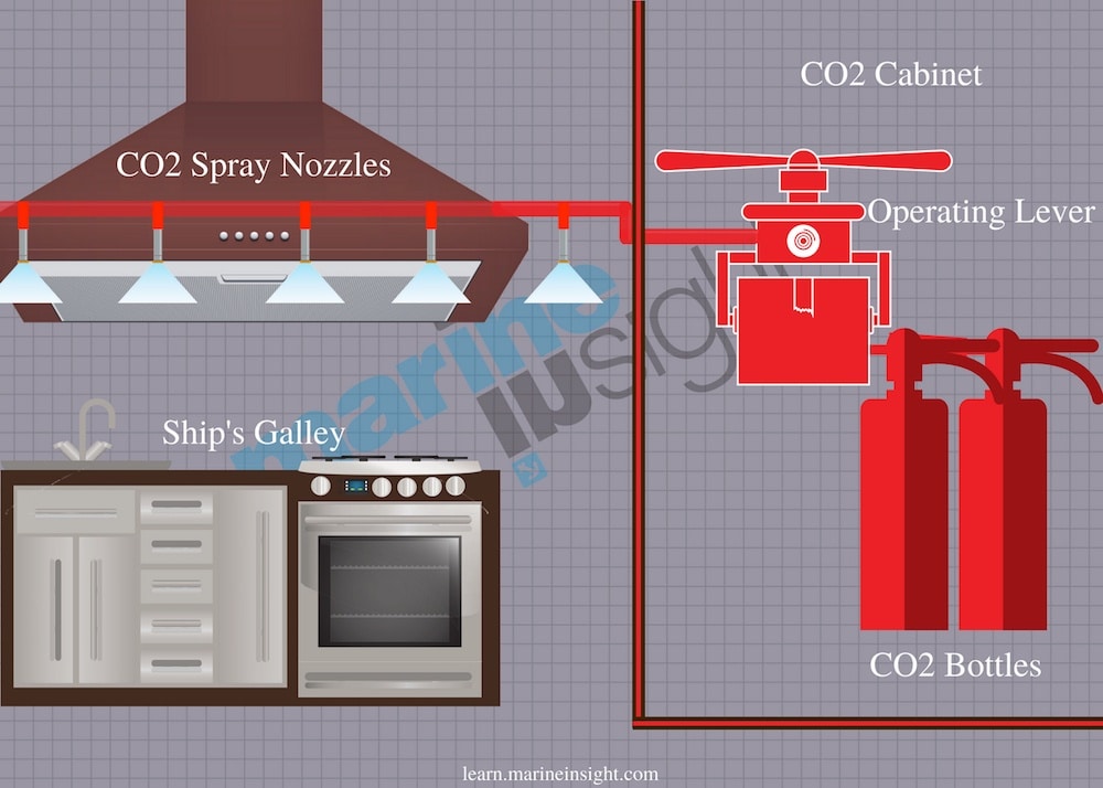
Galley CO2 Fire Extinguishing System
The galley exhaust duct has a local CO2 system consisting of a single CO2 cylinder which is located in a small compartment adjacent inside the galley.
It provides an extinguishing capability in the event of a fire in the galley and galley exhaust duct. In the case of fire, switch off the galley fans and close the uptake fire damper in the galley deckhead.
The emergency stop switch for the galley fans should be located outside the galley, and also on the bridge and in the fire control station.
Evacuate all personnel from the galley, then release the CO2 cylinder by opening the cylinder storage door and opening the cylinder outlet valve fully. Exit from the galley and close the galley entrance door.
Related Read: 12 Things You Must Do Before Operating Ship’s CO2 Fire Extinguishing System
Some of the galleys are also equipped with deep fat fryer wet chemical extinguishing medium for a deep fat fryer. Fat fryers are particularly difficult to protect due to the amount of stored heat that is contained in a large quantity of cooking oil.
The deep fat fryer appliance in the galley is protected by a fixed fire suppressant system. The protection system is comprised of a single stainless-steel storage cylinder containing an extinguishing agent.
The cabinet is located in the galley and is activated by pulling a release handle located close by the system cabinet.
When activated, the chemical extinguishing agent is discharged into the fire extinguishing pipework. The discharge from the cylinder is led via piping to fixed spray nozzles. The extinguishing chemical has an expected storage life of twelve years.
The extinguishing wet chemical used is R-102 Ansulex Low pH Liquid Chemical.
Other Safeties In Accommodation
All the lockers and cabins in the accommodation are provided with door locks. These door locks have their individual keys and can also be opened by a master key which will be in custody of the Master.
The stairways have anti-skid stripes to prevent tripping and falling and also handrails for support. Handrails are also provided along alleyways each deck for support during rolling and pitching.
Disclaimer: The authors’ views expressed in this article do not necessarily reflect the views of Marine Insight. Data and charts, if used, in the article have been sourced from available information and have not been authenticated by any statutory authority. The author and Marine Insight do not claim it to be accurate nor accept any responsibility for the same. The views constitute only the opinions and do not constitute any guidelines or recommendation on any course of action to be followed by the reader.
The article or images cannot be reproduced, copied, shared or used in any form without the permission of the author and Marine Insight.
Do you have info to share with us ? Suggest a correction
Latest Shipboard Guidelines Articles You Would Like:


Subscribe To Our Newsletters
By subscribing, you agree to our Privacy Policy and may receive occasional deal communications; you can unsubscribe anytime.
Web Stories