High Speed Centrifuge on Ship: Construction and Working
A high-speed centrifuge is a type of separator which is used on a ship to remove contamination from liquids such as fuel and lube oils. It is imperative to carry out this treatment in order to remove solid impurities and water before they are supplied to the marine engine. Thus, the task of the centrifuge is to remove solid contamination from liquid and to remove undesirable liquid (water) from useful liquids (fuel).
Principle of Working
The separation principle of high-speed centrifuge depends on the difference in the specific gravity of two different liquids. To understand, let’s take a settling tank where fuel is stored and because of the difference in the gravity of water and fuel (water is heavier) the water gets collected at the bottom part of the due to the effect of gravity.
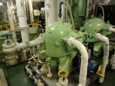
Mathematically this process can be represented by:
Fs = ∏/6x D3 (ρw-ρo) g
Where Fs is the separating force, ρw is the density of water, ρo is the density of oil and “g” is gravitational force.
Now if we convert the tank into a conical rotating object, then the gravitational factor g will be replaced by the centrifugal force ω2 r, where ω2 is angular velocity of rotation and r is the effective radius.
Fs = ∏/6x D3 (ρw-ρo) ω2 r.
Now the separating force will be much higher in the centrifuge as compare to a settling tank.
Construction of High-Speed Centrifuge:
Basic components of the centrifuge are as follows:
Exterior framework:
The exterior framework is normally made up of cast iron which supports the internal bowl and disk parts and carries water line, feed line, and outlet line connections.
Bowl and disk:
There are bowls inside the frame, which can be a solid assembly operating noncontinuous and have space enough to retain the separated sludge. There can also be an arrangement in which the upper and lower parts are separated for discharging the accumulated sludge by a continuous operation. These parts are normally made up of high tension stainless steel.
Vertical shaft:
The Vertical shaft is used to transform the electrical motor output into rotational motion for rotating the bowl at high speed through spur gear and horizontal shaft or belt. The material used for vertical shaft construction is an alloy of steel.
Attached Gear pump:
A general construction of centrifuge consists of a horizontal shaft driven attached supply or discharge gear pump.
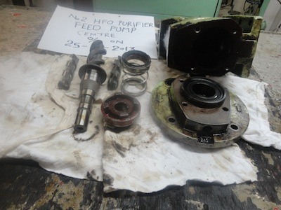
In some system, an external supply pump may be installed in place of the attached pump.
The horizontal shaft or belt drive:
The electrical motor drives the horizontal shaft through clutch pads and is used for transmitting the rotational motion to bowl assembly.
A special belt having elastic character is used in some models in place of horizontal shaft, thus removing the use of the gear assembly. The horizontal shaft material is a special alloy of steel.
Spur gear:
A spur gear is placed between the horizontal and vertical shafts for the transfer of rotational motion. These gears are manufactured from the special aluminum bronze material.
Clutch or friction pads:
An electric motor will get overloaded if it is connected directly to the bowl assembly for the rotation of the same as the complete assembly is very heavier. To avoid this, clutch or friction pads and drum assembly are installed on the horizontal shaft. Normally the number of pads varies from 2 to 4 depending upon the frequency supply to the motor
As the motor starts, the pads inside the drum moves out gradually due to centrifugal force and cause friction in the internal wall of the drum resulting in rotation of the shaft and the bowl gradually without overloading and damaging the motor and gears.
Automation:
Apart from the mechanical parts, the latest centrifuge comes with full automation circuit involving three-way valves, detectors, monitors, transducers, solenoid valves, pneumatic valves etc, along with a control panel, which ensures the centrifuge fulfills all the criteria required for operation in an unmanned engine room.
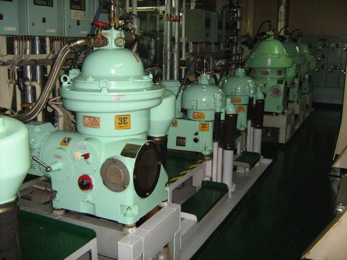
Types of Centrifuge:
There are normally two types based on the application:
1) Purifier: When a centrifuge is arranged for separating two liquids of different densities, for e.g. water from oil, it is known as a purifier. The main component of purifier is correct size gravity disc or dam ring which is responsible for creating an interface between the oil and water.
2) Clarifier: When a centrifugal is arranged to remove only impurities and a small amount of water, it is called as the clarifier. Since it is used mainly for that fluid were mostly solid impurities are to be removed, gravity disc is not used in clarifier; instead a sealing ring is used to keep the impurities intact unless desludged.
The basic operations of clarifier and purifier are:
– It contains a stack of disk numbering up to 150 and is separated from each other by a very small gap. A series of holes are aligned in each disk near the outside edge which permits the entry of dirty oil.
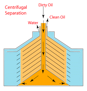
– Due to the difference in gravity and centrifugal force, the heavier impure liquid (water) and particles move outside and lighter clean oil flows inwards and gets separated.
– The collected sludge and impurity can be discharged continuously or at a time intervals, depending upon the construction, automation, and system incorporated
– In a purifier, before introducing the oil, water sealing is established so that oil fill should not flow out through the heavy liquid outlet
– In clarifier, there is no heavy liquid outlet for discharging separated water hence water sealing is unnecessary
– Feed rate and temperature of the feed is extremely important for purification. For normal oil, one stage purification is enough, but for oil containing heavy sludge or catalyst mixture, multiple purifiers are used in either parallel (preferred) or series to get better results
– The new age purifiers/ clarifiers are automatically desludged at a regular interval (by use of timer and controllers. A discharge detectors on the sludge side monitors the sludge side and provides alarm signal if any abnormality is detected
You may also like to read – What Is Quick Coupling or Quick Connect Coupler?
Do you have info to share with us ? Suggest a correction
Latest Shipboard Guidelines Articles You Would Like:

About Author
An ardent sailor and a techie, Anish Wankhede has voyaged on a number of ships as a marine engineer officer. He loves multitasking, networking, and troubleshooting. He is the one behind the unique creativity and aesthetics at Marine Insight.
Subscribe To Our Newsletters
By subscribing, you agree to our Privacy Policy and may receive occasional deal communications; you can unsubscribe anytime.













to anish,
if my purifier is overflowing and need to change gravity disc, do i choose bigger size or smaller size diameter.
Dear Jason,
If the gravity disc is too large and/or the outlet line back pressure is too high, the interface will be too close to the periphery of the bowl and fuel will be carried over into the water outlet. Conversely, if the gravity disc is too small and/or back pressure is too low, the interface will be too close to the centre of the bowl and purification will be inefficient, with water being carried over in the purified fuel.
Practically, you should reduce the diameter of the GD only after checking the required size from the makers manual in Selection Nomogram for gravity disc (A graph with SP. Gravity, Sp. Temperature, GD diameter and feed rate as the main comparing parameter).
To anish,
Million thanks to you, your message was very helpful. As a new engineer, i still have a lot of question that’s confused me sometimes and your site contribute such a big help. Thank you.
Jason
My problem is water is mixed on the oil I want know if it is cause by purifier, cause the sump of my engine has not been purified for a long time. Before my oil analysis is normal but when the purifier is operational the content becomes a little high. What would be the problem??
@ Anjo: The most common reason for such problem are-
1. leaking sealing water valve
2. Problem in interface. Check fuel properties and change gravity disk size after referring Manual.
Thanks sir it is really helpful.
I wanna know why interface line at gravity disc is required in purifier .. let say what if the interface line is closed by somehow and let the water and oil discharge from their respective lines ??
interface required to seprate water and oil
if interface closer water goes with oil through gravity disk hole
which is undiserable
Dear sir,
What is sealing water in purifier. Please explain
@ Bala Krishnan: The main function of sealing water is to form an interface between oil and sludge. Without this sealing, the oil particle will be lost with sludge and water
Could you explain more clearly your comment on the gravity ring and back pressure. I assume it is the inner diameter gap that gives the back pressure on the water seal. When decreasing this gap, which is required for high density fuel, this would then give higher back pressure of the water seal against the heavier fuel. Is this the way it works as you say its the opposite . Ref October 2013. I’m still trying to get my head around how the gravity ring works.
I jst wanna know…. What is neutral phase in purifier n where the hydrostatic balancing takes place in purifier….
i want better explanation on purifier can u please help in this regard .I understand basics but i am very crusious to have command over it
There are many articles on purifier on marineinsight… please do use the “search bar” at the top right corner..
What will happen to the interface between oil nd water as the temperature changes
what are maintenance of centrifugal separator
what is the overflow of oil in purifier and why does it takes place
How to purify oil if its density is more than 1??
I want to know why exactly does the speed drop during discharge?
I need a centrifuge in our virgin coconut oil manufacturing plant. Where can I get the machine that can do the job
Please what could be the Problem if purifier automatic desludge system is not desludging ??
What will be the first action if you find that purifier is over flowing?
Thabks for the information sir.
I just want to know, what are the safties in case of attached gear pump (feed pump)?
One of the important safety in the attached pump is quick coupling, which connects the purifier and pump shaft. In case the pump is stuck, the coupling breaks avoiding any harm to separator shaft/gear assembly and prevent motor overloading.
dear sir
what is the principle of the purification process?
@Ahmir: Please check this video course – https://learn.marineinsight.com/course/purifier-course/
I wanna reply some questions but i don’t know how to, so i will write it as a command. Firstly, the speed of separator increases during discharge to maintain a good gravity for sludge to be thrown out. Hence the belt might be the problem when separator doesn’t discharge. There are 3 kinds of water going into the separator; seal water, closing water and discharge (shock) water. If the separator separates but won’t discharge, most probably discharge water filter is clogged. Other than that it might be the o rings, teflon valves etc.
To check the functioning of separator, you can check the sludge discharge, if you see a little amount of water flowing intermittently and some sludge, it means it works well. If you see a continuous flow of oil, it means the separator doesn’t work and it discharges whatever it admits to sludge. If you see water coming out (splashing) 90 % it is the brass body at the bottom of the bowl.
For maintenance, there are 2 different types of maintenance, intermediate and main maintenance. In intermediate maintenance o-rings and teflon bodies are changed, docs and all other parts are cleaned (preferably with diesel oil). And for main maintenace , it is internediade maintenance + change of friction pads, belt etc.
Different brands have different intervals for intermediate maintenance but it’s usually unlikely for a separator to operate well during that interval, they usually start malfunctioning before maintenance time, so you do the intermediate maintenance when it starts not to separate.
@Orhan: Thank you Orhan for your valuable input.
1.How does the gravity disc make interface?
sir can anyone please tell me how gravity disc creates an interface
Please let me know difference between alfalaval Mitsubishi and westfalia purifier
please i need the link which enables me to find monograph chart
Gravity disc size of heavy oil and diesel oil…. Which is higher in size???