

Water-Mist And Sprinkler Systems On Passenger Ships
The role of fire-fighting systems on ships cannot be more emphasized. Time and again, deadly fires have ravaged merchant ships at sea, away from the land without any hope of shore-based assistance and have caused large-scale destruction to the ship, cargo and, even worse, resulted in the loss of human lives.
Now imagine such a scenario on a passenger ship with thousands of lives on board; the mere thought is terrifying as the loss of lives could be potentially much more. For this reason, it is critical for the cruise ships to be fitted with means of fighting fires, both in the passenger areas and crew areas, including technical spaces.
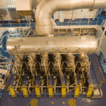
As in the case of cargo ships, even here, the most likely place for a fire to potentially start is the engine room. The heat from running machinery and exhaust, oily surfaces and abundant air supplied through blowers make it a very hazardous and vulnerable space for fires to start. If not curbed or controlled initially, a fire can spread rapidly to other areas around the ship, causing large-scale devastation and creating havoc.
It is for this very reason that cruise ships are fitted with multiple systems for fire-fighting. For example, many cruise ships are equipped with a water-mist system, in addition to the carbon-dioxide fixed fire-fighting system (for technical spaces) and sprinkler system (for crew and passenger areas). However, many latest passenger ships use only the water-mist system for all areas (crew, technical and passenger spaces).
For machinery space fires on these ships, the water-mist often serves as the primary means of fire-fighting. In contrast, the CO2 is only used as a backup in cases where the fire has become large and uncontrollable, leaving no option but to release it.
In the water-mist system, water in the form of a very fine mist is discharged from the nozzles or sprinklers installed on top of the protected equipment or area.
The advantages of using water in this form for fire-fighting as compared to the traditional sprinkler system are: –
- Increased area of coverage and better distribution of the fine water-mist
- Better penetration to the seat of the fire
- Rapid cooling of the seat of the fire and surrounding areas
- Rapid evaporation of the micro-fine droplets to steam helps in smothering the fire (oxygen-starvation).
- Little to no risk of any damage to equipment as water is in the form of a fine mist.
- Lesser consumption of water because of reduced droplet size as compared to the sprinkler.
Its relative advantages over the traditional carbon-dioxide fixed fire-fighting system are: –
- Can be released much more quickly than CO2, which requires perfect sealing and evacuation of personnel.
- This saves precious time and minimizes further spreading of fire.
- No risk of the presence of gas pockets after the fire is extinguished, unlike CO2.
- No risk to life in case of release (accidental or otherwise)
- Unlike the CO2 system, which requires bulk release, the water-mist is released to protect only the area necessary/equipment affected by the fire.
- The refilling process is much easier and costs much less compared to CO2 system.
- No specialized shore-based assistance is required for maintenance, unlike CO2 system, which requires refilling and pressure-testing of the bottles every few years.
The Hi-Fog water-mist system
This is a type of water-mist fire-fighting system which is developed by Marioff Corporation and which are seen installed on a few passenger vessels.
It basically consists of two individual units. A Master unit at the forward of the ship and a Slave unit at the aft. Each unit has the arrangement as per the below figure.
Operation of the Hi-Fog water-mist system
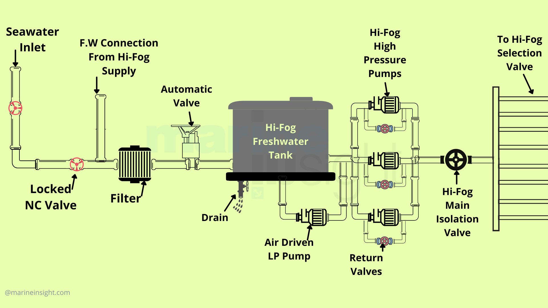
The freshwater required for the system is stored in a tank. This tank has a level gauge and high/low-level float switches. The water in this tank is replenished according to its level.
When the level of water goes down, it activates the low-level float. This sends a signal to the automation to start the Hi-fog supply pump (not shown in the above figure) and also to open an automatic valve in the filling line of the pump.
This pump supplies/replenishes fresh water to the tank from one of the ship’s technical water tanks via a filter and automatically stops when the desired level is reached. This also closes the automatic valve.
The supply pump operation (cut-in/cut-off) can be tested as a monthly routine by draining the tank manually through a drain valve provided at the bottom of the tank. This drain line is connected to the bilges.
In the normal condition, a pressure of 18-24 bar is always maintained in the Hi-fog system. This is ensured by an air-operated low-pressure diaphragm pump whose purpose is to compensate for small leaks and losses.
In case the pressure drops below 18 bar (in case of fire when Hi-fog releases or a major leak), the high-pressure pumps automatically start. These are positive displacement pumps that can raise the system pressure to around 140-150 bar when operated. There are usually 8-10 pumps but I have only shown 3 pumps in the above figure, for ease of understanding.
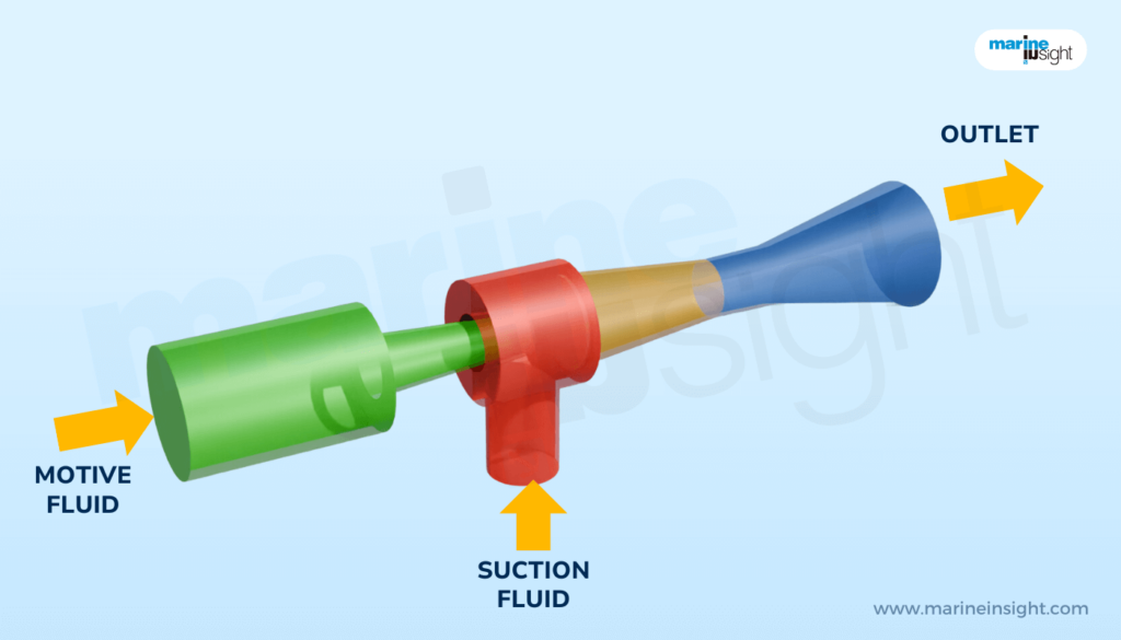
Each high-pressure pump is provided with a relief valve on the discharge side. This is to avoid damage to the pump and the line in case of operation of the pump with the main isolating valve closed, such as during the testing of the pumps. The relief valve operates to release the excess pressure back to the tank or suction side of the pump.
The high-pressure pumps are always in automatic mode. The pumps once started automatically, have to be stopped manually once the fire is extinguished. Thereafter, an automatic drain valve (not shown in the figure) drains the Hi-fog line to bring the pressure down from around 150 bar to the normal value of 18-24 bar.
The high-fog common main isolating valve on the discharge side of the pumps is always kept open. During routine monthly testing of the high-pressure pumps, the main isolating valve is manually closed and the pumps are switched to manual mode.
The pumps thus started, are tested for the build-up of pressure, any abnormal noise/vibration and operation of the relief valve. The oil level inside the pumps should also be checked during machinery rounds and replenished as required. Oil replacement should be done as per PMS.
Master, Slave Operation and Water Cylinders
In case of a major conflagration anywhere on the ship, the forward unit which is set as Master, operates first. If the fire does not come under control, the Master unit (forward) sends a signal for the Slave unit (aft) to operate.
If in case, the fire still does not come under control, some ships are provided with water cylinders (usually 10 numbers each containing 50 litres of water) as additional freshwater supply.
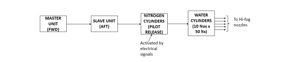
Nitrogen pilot cylinders are provided which act as an actuation mechanism for opening/releasing the water cylinders. In a case of a situation where despite both the Master and Slave unit together being unable to extinguish the fire, the nitrogen is released with the help of electrical signals, which in turn, actuates and releases/opens the water cylinders. Pressurized water then goes to the Hi-fog heads.
In addition to all the above, a seawater supply line (usually from the fire line) is also provided to the Hi-fog system. This is in the case where the freshwater in both the Hi-fog tanks (forward and aft), in the technical water tanks and in the water cylinders might not suffice. Two valves are provided for seawater supply, which is in a normally closed (NC) position.
If seawater has been used, once the fire is extinguished, the lines have to be thoroughly flushed with fresh water to minimize the possibilities of corrosion and scaling due to seawater, before filling with fresh water and putting the system on standby for use.
Section valves and nozzles
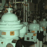
The Hi-fog system has many section valves for supply to machinery spaces and accommodation. Each section valve caters to a particular location, for example, there is one section valve for each diesel generator, each boiler, each purifier room (forward and aft), each incinerator and for accommodation areas, a section valve for each deck.
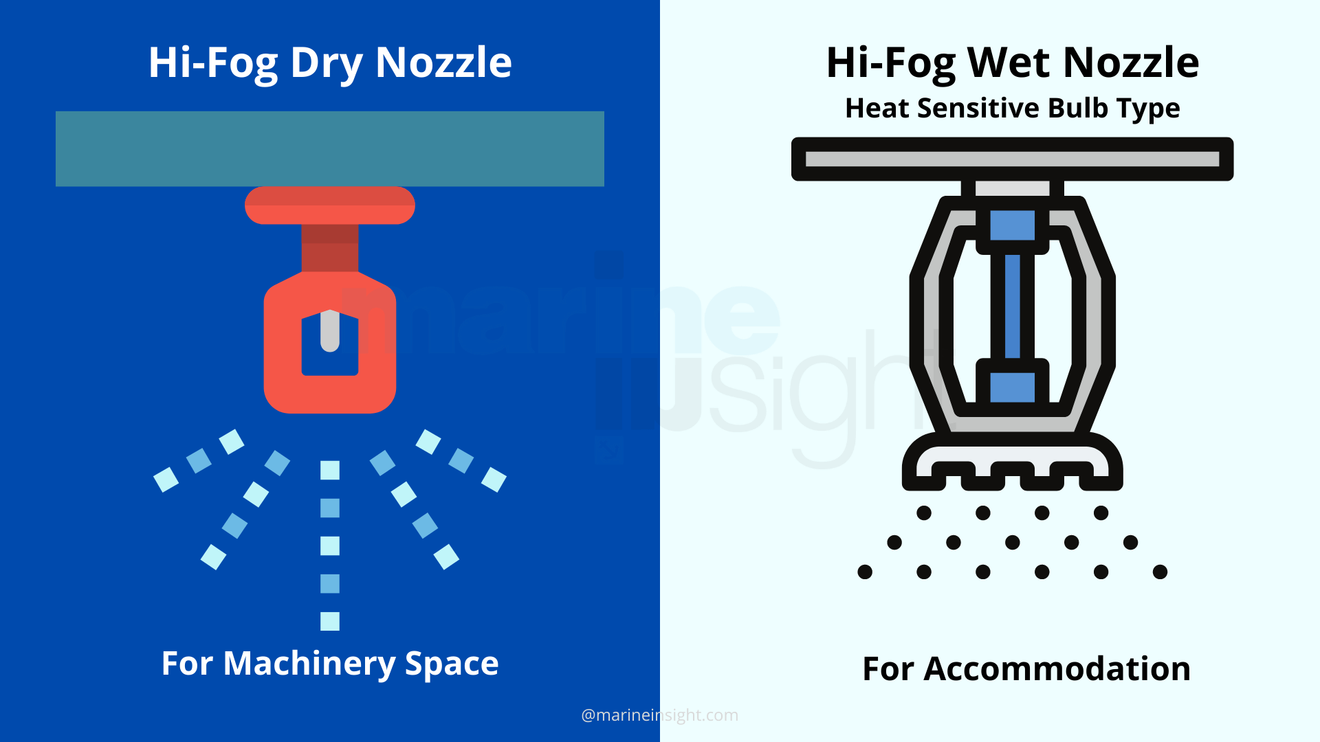
There is a difference between the section valves, lines and the design of the Hi-fog nozzles provided in the machinery spaces and the ones provided in the accommodation areas.
The section valves in the machinery spaces are normally closed (NC) and can be opened either manually or by means of push-button from the engine control room.
This means that the Hi-fog lines in the machinery spaces are dry in the normal condition and only when there is a fire, the valve is opened by the watchkeepers and water supplied to the Hi-fog nozzles.
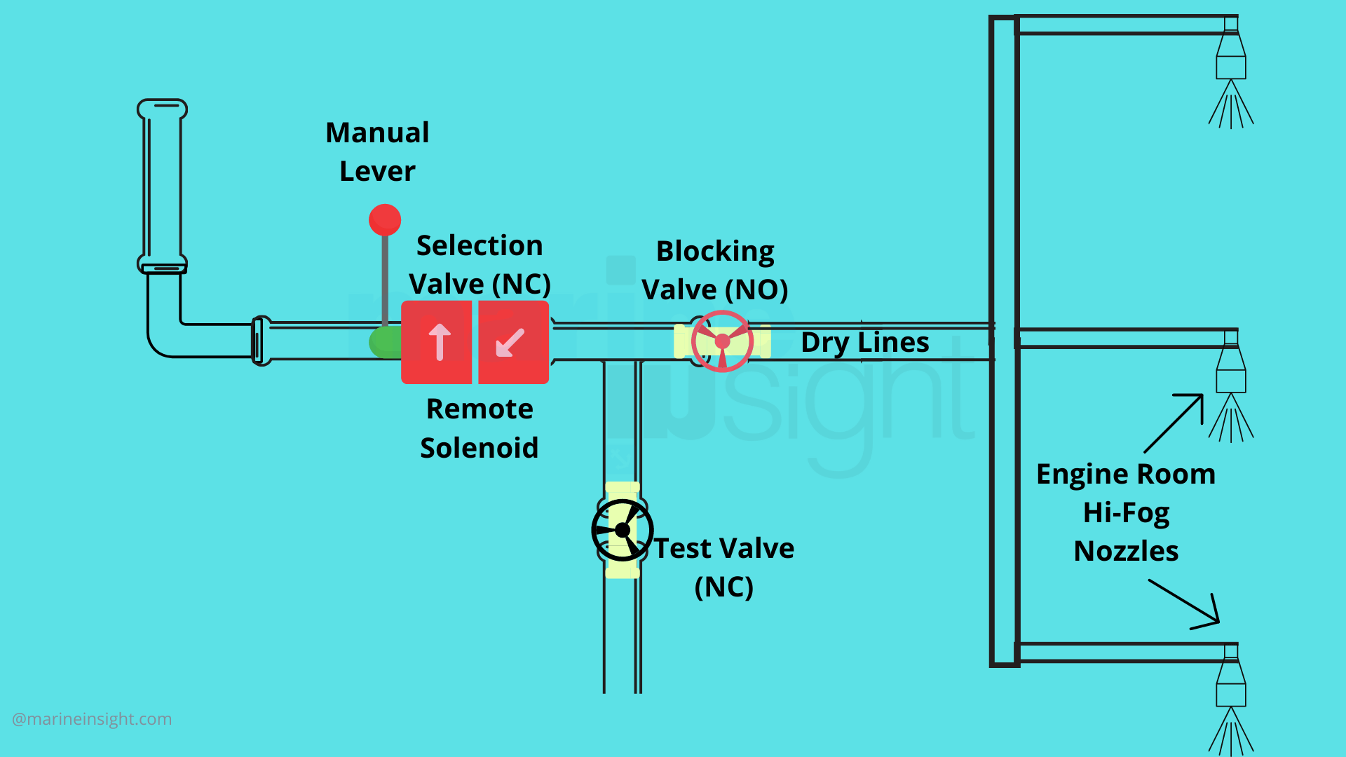
Testing of machinery space section valves
Testing of the section valves is carried out as per PMS. The Blocking valve (shown in the above sketch) supplying the water to the Hi-fog nozzles is shut and the test valve (also shown) is opened. Then the section valve is opened (either locally or remote) and water flow is checked.
The accommodation section valves are normally open (NC) which means that the lines are always wet, i.e., the water is always available up to the nozzle or sprinkler head. The nozzles themselves are of the bulb-type, a bulb filled with a heat-sensitive fluid that expands and breaks in case of temperature increase due to a fire, thus releasing the water.
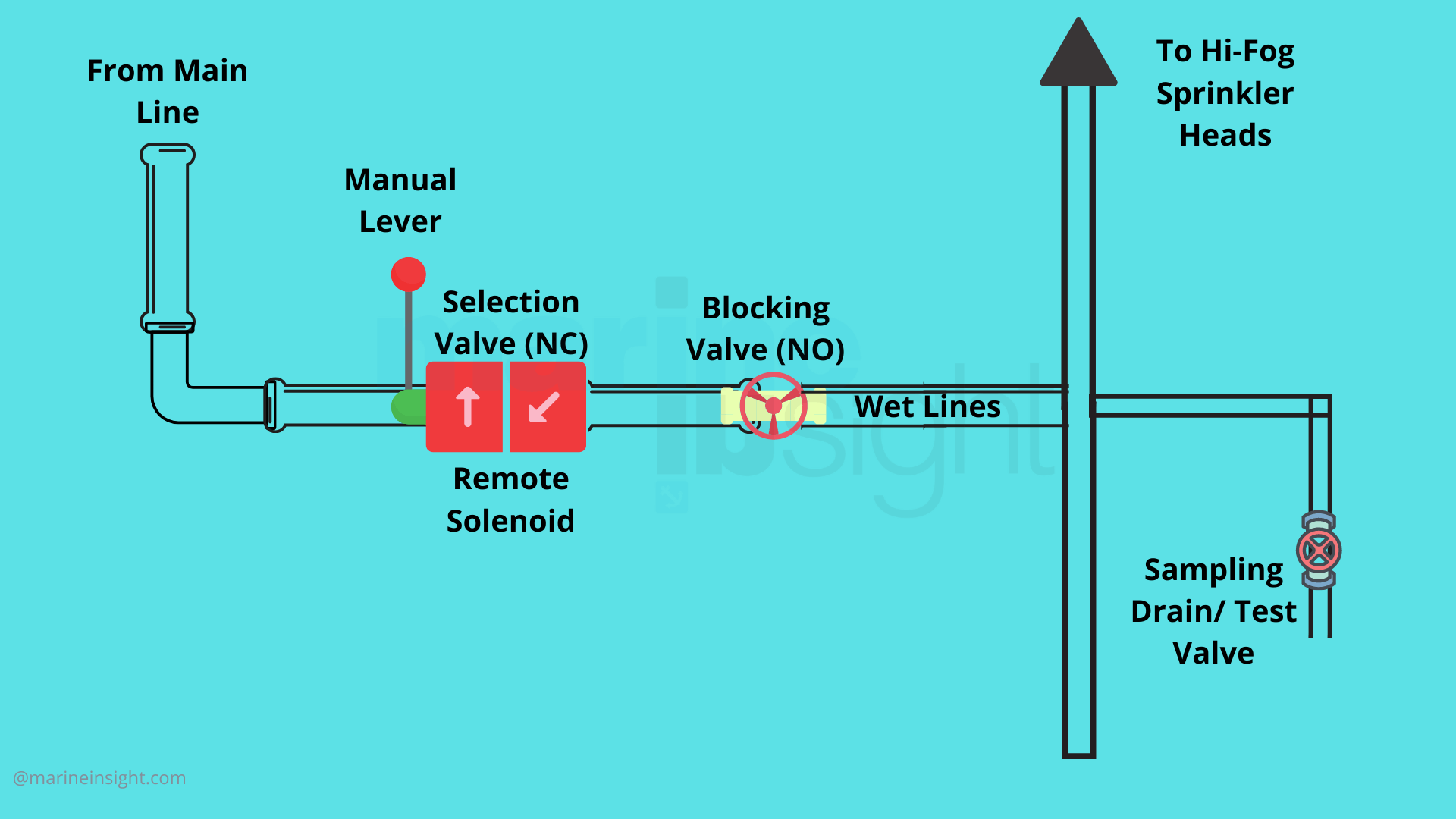
Hi-fog distribution in accommodation areas of a passenger ship
The reasons for this difference are:
- The accommodation areas including passenger cabins are not always occupied. Therefore, in case of a fire, the system should be designed in such a way so as to operate quickly & automatically to minimize damage, unlike machinery spaces and engine control rooms which are always manned.
- The machinery spaces are at a much higher temperature than the accommodation areas. So, if wet lines and heat-sensitive bulb-type nozzles are used, there might be an accidental release of Hi-fog due to breaking of the nozzles under higher temperatures especially in hot engine-room areas such as near the DGs and purifier rooms, even without any actual fire.
Therefore, the machinery spaces have dry lines and the accommodation has wet lines.
However, in both cases, the solenoid-operated section valves have to be closed manually by push-buttons from the engine control room, once the fire is extinguished. For the accommodation, these valves are opened after the replacement of the broken nozzles and are always kept open thereafter (NO position). In the engine room, they are of the NC type.
For the machinery space section valves, in addition to operation from the engine control room, the local push-button release is also possible. This is provided for redundancy purposes and in order to save time in case of a fire or a potential threat of fire.
The Hi-fog system as explained above is found in many modern and newer ships and provides the versatility of the ability to fight fires both in the accommodation areas as well as engine rooms. The system is widely accepted because of its efficiency, redundancy, little to no risk of exposure or evacuation and ease of operation.
Due to the above advantages, the system has found its use as a retrofit in many older passenger ships as well. However, due to higher retrofitting costs and the complication of remodelling and restructuring, the use of Hi-fog in older ships is generally restricted to high-risk areas in the machinery spaces such as boiler, DG, purifier & incinerator rooms
For accommodation areas, a more traditional sprinkler system is used.
Sprinkler system
Sprinkler system for accommodation fire-fighting in older passenger vessels
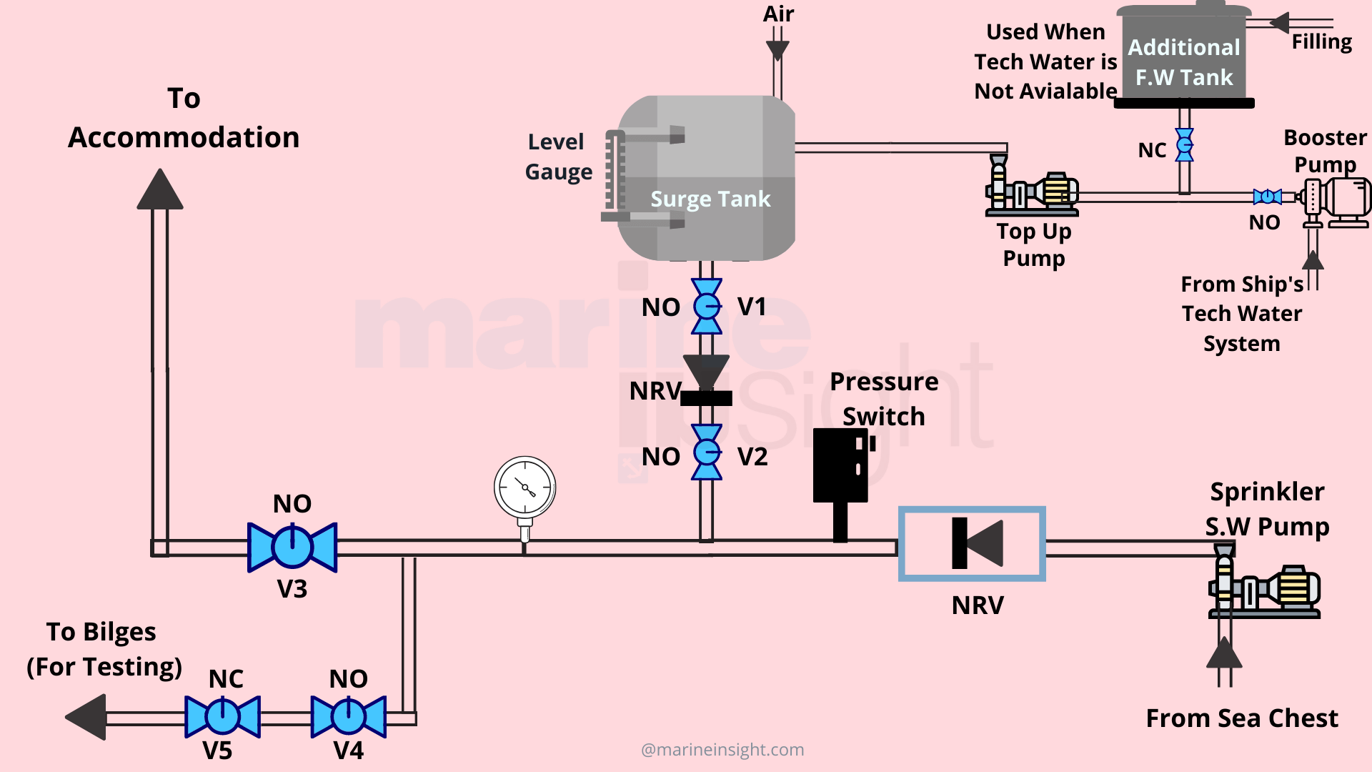
The sprinkler system shown is used for fire-fighting in accommodation areas on older passenger ships. This system is designed for use with freshwater normally supplied from one of the technical water tanks as well as from seawater in case of emergency. The system components are: –
Surge Tank: This is a pressurized vessel that is used to maintain the system pressure at about 10-12 bar. It has an air supply and a level gauge.
Additional freshwater tank: This as the name suggests is a supplementary source of freshwater and is only used when the main freshwater tank is empty or not available. This tank is filled with technical water from the ship’s TW system.
Booster pump: This pump supplies technical water from the designated tank to supply water to the topping-up pump.
Topping-up pump: This pump runs in series with the Booster pump in normal situations but can also run independently to top-up the system (surge tank) directly from the additional freshwater tank when the designated TW tank or booster pump, are not available.
Sprinkler SW pump: In case of emergency, the system can also be operated on seawater through the sprinkler SW pump. Also, the pump cuts in automatically whenever the system pressure drops below 5 bar through the pressure switch.
Non-return valves: There are two NRV’s provided. One is in the SW pump discharge line in order to prevent backflow & thereby loss of system pressure via the SW supply line. Another one prevents backflow to the surge tank.
Pressure Gauge: It indicates the system pressure.
Line valves: These are usually butterfly valves with limit switches for remote indication for an OPEN or CLOSE position. There are five valves namely V1, V2, V3, V4 & V5.
Normal set-up
During the normal set-up of the system, the FW level in the surge tank is maintained at about 3/4th as can be observed from the level gauge. A column of air must be maintained inside the surge tank. This must be checked by the watchkeepers during their routine rounds as it will help in maintaining the system pressure and also prevent the surge tank from becoming too full with water.
The booster pump and topping-up pump are kept in automatic mode and the valves are lined up such that the system can supply water to the various sprinkler stations in the accommodation area from where water is further supplied to sprinkler heads in various cabins or guest spaces. The set-up is as below: –
- VALVE V1 IS IN OPEN CONDITION
- VALVE V2 IS IN OPEN CONDITIONVALVE
- V3 IS IN OPEN CONDITION
- VALVE V4 IS IN OPEN CONDITION
- VALVE V5 IS IN CLOSED CONDITION
In case of a fire, the booster and topping-up pumps automatically start as the water level in the surge tank goes down. If the fire is not extinguished, the pumps will keep running until the low level of the designated technical water tank. Beyond this, the additional freshwater tank can be put to use via the top-up pump, by opening a valve.
When the additional freshwater tank empties, the system pressure drops and the sprinkler seawater pump starts automatically through the signal from the pressure switch, to supply seawater for fire-fighting.
If seawater is used, the system needs to be flushed with freshwater before reuse.
System Testing
The system must be tested as per PMS and reported. This is important so as to ascertain the proper working of all the pumps, valves and pressure switches. The top-up pump and booster pump must be put to manual or off-position before in order to test the sprinkler seawater pump operation. The system is set up as below: –
- VALVE V1 IS IN CLOSED POSITION
- VALVE V2 IS IN CLOSED POSITION
- VALVE V3 IS IN CLOSED POSITION
- VALVE V4 IS IN OPEN POSITION
- VALVE V5 IS IN OPEN POSITION
Since valve V4 is already in the open position, when valve V5 is opened as per the sequence mentioned above, the water in the pipeline between the closed valves V2 and V3 starts draining to the bilges. This drop in pressure can be observed through the pressure gauge. When the pressure drops below 5 bar, the pressure switch causes the seawater pump to cut in.
At this point, the pump must be manually stopped and V5 closed immediately. All other valves should be put back to their normal positions and all pumps should be put back to automatic.
Water quality testing
It is important to test the water quality for both the water-mist as well as the sprinkler system from time to time. For the water-mist, the samples are taken from the test/draining valves and for the sprinkler system, they are taken from various sprinkler stations. It is tested for pH, conductivity and chlorides.
If chloride content is found high, the system needs to be drained, flushed and refilled with technical water to prevent/minimize corrosion and decay of pipelines and fittings.
Summary
Both water-mist and sprinkler systems are critical keeping in mind the safety of the ship, crew, passengers and readiness in tackling fire emergencies onboard.
The water-mist system, in fact, has super ceded the sprinkler system in many modern passenger vessels due to its higher efficiency, less water consumption, quick detection of fire and release, lower operational costs, little to no risk of damage to area/equipment, technological advancement, versatility and adaptability (the same system can cover all areas of the ship).
It has even super ceded the traditional fixed fire-fighting CO2 systems in terms of quick releasing capabilities and no obvious threat to life on release. It is much more economical and easier to replenish the system after use and to carry out routine maintenance. Also, it gives more flexibility of operation.
Due to these reasons, the water-mist has now become the preferred or primary source of fire-fighting on cruise vessels, machinery spaces included. The CO2 system still exists though, but only as a backup and the last resort in case of an uncontrollable machinery space fire.
Many older passenger vessels too, have retrofitted water-mist systems on board in addition to existing sprinkler systems. But it looks like sprinkler systems are being phased out with increasing acceptance for water-mist and technological advancements.
You might also like to read:
- How Ships are Protected from Lightning; Ships Earthing System
- How Are Cruise Ships Powered?
- Engineering Department Onboard Cruise Ships; A Detailed Guide
- How Do Cruise Ships Get Fresh Water?
- Titanic vs Modern Cruise Ship: How Ships Have Evolved
Disclaimer :
The information contained in this website is for general information purposes only. While we endeavour to keep the information up to date and correct, we make no representations or warranties of any kind, express or implied, about the completeness, accuracy, reliability, suitability or availability with respect to the website or the information, products, services, or related graphics contained on the website for any purpose. Any reliance you place on such information is therefore strictly at your own risk.
In no event will we be liable for any loss or damage including without limitation, indirect or consequential loss or damage, or any loss or damage whatsoever arising from loss of data or profits arising out of, or in connection with, the use of this website.
Do you have info to share with us ? Suggest a correction
Disclaimer :
The information contained in this website is for general information purposes only. While we endeavour to keep the information up to date and correct, we make no representations or warranties of any kind, express or implied, about the completeness, accuracy, reliability, suitability or availability with respect to the website or the information, products, services, or related graphics contained on the website for any purpose. Any reliance you place on such information is therefore strictly at your own risk.
In no event will we be liable for any loss or damage including without limitation, indirect or consequential loss or damage, or any loss or damage whatsoever arising from loss of data or profits arising out of, or in connection with, the use of this website.
Latest Marine Technology Articles You Would Like:
- 10 Harmful Effects Of Impure Air On Ship’s Machinery

- 10 Important Things to Check While Starting Fuel Oil Purifier on Ships
- 10 Noteworthy LNG-Powered Vessels
- 10 Points for Efficient Turbocharger Operation On Ships
- 10 Practical Tips to Handle Engine Room Pumps
- 10 Precautions to Take Before Operating Controllable Pitch Propeller (CPP) on Ships


Subscribe To Our Newsletters
By subscribing, you agree to our Privacy Policy and may receive occasional deal communications; you can unsubscribe anytime.