

Ship’s Main Engine Lubrication System Explained
Lubrication is essential for any kind of machinery onboard ships. Lubrication of the Main Engine is responsible for lubricating and cooling the internal parts, which are acting relative to each other creating friction and heat, resulting in overheating of parts. Lubrication not only provides cooling and but also the removal of any debris or impurities.
Types of Lubrication Systems
There are a few main types of lubrication systems used:
- Hydrodynamic Lubrication: In this type of lubrication, the oil forms a continuous oil film of adequate thickness between the moving surfaces. The film is formed due to the motion of the moving parts and the self-generated pressure. For example, journal bearings of Main Engine have hydrodynamic lubrication. A film is formed between the main bearing and the journal of the crankshaft with the help of a wedge formed by the rotating shaft. Thrust bearings with a tilted pad design also have this type of lubrication as they form a converging wedge to obtain hydrodynamic lubrication.
- Hydrostatic Lubrication: Where oil film cannot be formed due to the motion of moving parts, the oil pressure has to be supplied externally. Such type of lubrication is known as Hydrostatic lubrication. For slow-moving heavy parts, their relative motion is not enough to provide self-generated pressure for lubrication and hence pressure is provided externally with the help of a pump. For example, many crosshead bearings design requires an additional crosshead lubrication pump to boost the pressure for crosshead bearing lubrication because the pressure cannot be self-generated.
- Boundary Lubrication: In this type, there is a thin film between two rubbing surfaces, which might have a surface contact. Boundary lubrication is used because of relatively slow speeds, high contact pressure and rough surfaces. For example, boundary lubrication in main engines occur during starting and stopping due to the above-mentioned conditions.
- Elastohydrodynamic Lubrication: In this type of lubrication, the lubricating film thickness considerably changes with elastic deformation of surfaces. This is seen in-line or at the point of contact between rolling or sliding surfaces, for example, rolling contact bearings and meshing gear teeth. Elastic deformation of metal occurs and there is an effect of high pressure on the lubricant.
Related Read: Ways to Monitor Bearing Condition and Reduce Bearing Breakdown in Modern Marine Engines
The main engine has three separate lubricating oil systems:
- Main lubricating oil system.
- Cylinder oil system.
- Turbocharger lubricating oil system
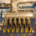
Main Engine: Main bearing, Gear drive and Piston Cooling Lubricating oil system
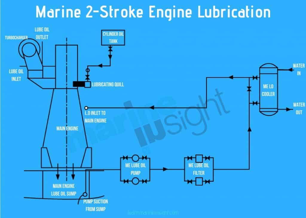
The main or crankcase lubrication system is supplied by one of two pumps, one of which will be operating and the other is on standby, set for automatic cut-in should there be a lubricating oil pressure reduction or primary pump failure. The main LO pumps take their suction from the main engine sump tank and discharge oil via the main LO cooler, which takes away the heat. An automatic backflushing filter unit with a magnetic core helps to remove any metal debris. The plate-type LO cooler is cooled from the low temperature central cooling freshwater system.
The supply pressure in the main lubrication system depends on the design and requirement and is generally around 4.5 kg/cm2. LO supply to the cooler is via a three-way valve which enables some oil to bypass the cooler. The three-way valve maintains a temperature of 45°C at the lubricating oil inlet to the engine. The main LO system supplies oil to main bearings, camshaft and camshaft drive.
Related Read: 8 Ways To Optimize Lubricating Oil Usage On Ships
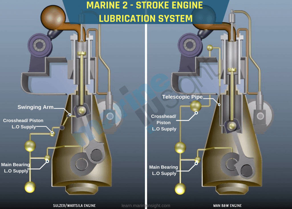
A branch of lube oil goes to an articulated arm or a telescopic pipe to the crosshead from where it does three functions
1) some oil travels up the piston rod to cool the piston and then comes down,
2) some oil lubricates the crosshead bearing and the shoe guides
3) the remaining oil passes through a hole drilled in the rod connecting to the bottom end bearing. A branch of lube oil is led to the hydraulic power supply unit for actuation of exhaust valves, to the thrust bearings, to the moment compensator and the torsional vibration damper. The cooling effect of the oil at the vibration dampers is important.
Operation of the Main engine Lubricating oil system
It is assumed that the engine is stopped but is being prepared for starting.
a) Check the level of oil in the main engine sump tank and replenish if necessary
b) Ensure that the low temperature central cooling system is operating and that freshwater is circulating through the main LO cooler
c) Ensure all pressure gauge and instrumentation valves are open and that instruments are reading correctly
d) Ensure that the steam heating is applied to the main LO sump tank if the temperature of the LO is low
e) Set the line and make sure all right valves are open. Normally it is assumed that main engine lubricating valves are left open
f) Select one main LO pump as the master (duty) pump and the other as the standby pump
Note: The main LO pumps have large motors and are generally fitted for autotransformer starting; after a start, the autotransformer must be allowed to cool down for 20 minutes before another start is attempted. Restarting is inhibited for 20 minutes between starts.
g) Keep the LO system circulating and allow the temperature of the system to gradually increase to normal operating temperature
h) Check the outlet flows from the individual units. Check that temperatures are similar and that all pressure gauges are reading correctly
i) When lubricating system temperatures and pressures are stable, the engine may be started. The main engine lubrication system is replenished from the main LO storage tank
Related Read: 10 Extremely Important Checks Before Starting Marine Engines
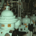
Main Engine LO purifier takes suction from main engine LO sump and purifies the oil. Its feed temperature is maintained around 90 degrees Celsius (as maximum density difference is achieved at that temperature) to allow efficient separation. The engine LO must be tested frequently in order to determine whether or not it is fit for further service. Samples should be taken from the circulating oil and not directly from the sump tank.
The main engine lubrication system also has a subsystem (depends if the main engine is cam-less or has a camshaft). In cam-less engines, a branch from the lube oil inlet to the main engine is provided to the hydraulic power supply unit. The function of HPS is to control the fuel injection and exhaust valve actuators hydraulically and also drive the cylinder lubrication units. In the main engine with a camshaft, a lubrication system feeds to camshaft roller guides and bearings, which actuates the exhaust valves and fuel pump.
Related Read: Construction And Working Of Marine Fuel Pump
Main Engine Lube Oil Sump Tank: It is located under the engine in the double bottom and is surrounded by cofferdams. A sounding pipe to know the level of lube oil in the sump is provided, along with a sounding pipe for cofferdam to know if there is any leakage. Cofferdam needs to be inspected on regular basis to know any signs of leakages. The main engine Lube oil sump consists of a level gauge, sounding pipe, air vent pipe, heating steam coil, manholes, suction pipe and valves for LO pump and LO purifiers.
Turbocharger Lubricating oil system
The turbocharger bearing lubricating system can be completely separate from the main engine lubricating system or can be feed through the main engine lubricating system, depending on the design. It is essential to have a separate filter for TC lubrication which is generally a duplex filter. From the duplex filter outlet, the turbocharger LO flows to the inlet manifold supplying turbochargers. The outlet of LO from turbochargers have a sight glass to make sure the flow is continuous. Under normal circumstances, a LO supply is always maintained to the turbochargers in order to ensure that they are always available for service and to prevent damage. A-LO supply must be maintained when the engine is stopped, as natural draught through the turbocharger will cause the rotor to turn. Hence, the bearings must be lubricated.
Related Read: Understanding Turbocharger Bearings and Lubrication On Ships
Cylinder Lubrication system
The load-dependent lubrication of the cylinders is performed by a separate cylinder lubrication system. Cylinder lubrication is required in order to lubricate the piston rings to reduce friction between the rings and liner, to provide a seal between the rings and the liner, and to reduce corrosive wear by neutralising the acidity of the products of combustion. The alkalinity of the cylinder lubricating oil should match the sulphur content of the HFO supplied to the engine. If the engine is to be run on low sulphur fuel oil for a prolonged period, advice must be sought from the cylinder oil supplier and the engine builder as to the most suitable cylinder oil to use.
Related Read: Important Lube Oil Properties to be Considered While Choosing Marine Lube Oil for Your Ship
The ability of an oil to react with an acidic reagent, which indicates the alkalinity, is expressed as TBN. It stands for Total Base Number. It should correspond to the sulphur percentage of fuel oil to neutralise the acidic effect of combustion. When high sulphur fuel oil is used for Main engines, a high TBN grade of cylinder oil needs to be used. When the main engine is a “change-over” to Low Sulphur Fuel Oil (LSFO) or Low Sulphur Marine Gas Oil (LSMGO), low TBN cylinder oil needs to be used.
There are two important systems used in modern lubrication systems:
1) Accumulation and Quill System (Sulzer Engines) and
2) Cylinder lubricating units pumping to orifices in the liner (MAN B&W).
The cylinder lubricating oil is pumped from the cylinder oil storage tank to the cylinder oil measuring tank which should contain sufficient LO for two days’ cylinder lubricating oil consumption. Cylinder lubricating oil is fed to the cylinder lubrication system by gravity from the measuring tank; a heater is located in the gravity line and pipe, pipes are electrically “trace heated” i.e. the outer surface of the pipe is maintained at a certain temperature. The heater and trace heating maintains a temperature of 45°C at the lubricating unit.
Before starting the Main Engine, it is necessary to pre-lubricate the liners. Pre-lubrication before the start can be made manually or by a sequence in the bridge manoeuvring system.
The following criteria determine the control:
- The cylinder oil dosage must be proportional to the sulphur content of the fuel
- The cylinder oil dosage must be proportional to the engine load, ie, the cylinder fuel supply
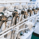
The quantity of cylinder oil injected at the individual injection points is controlled by the cylinder lubrication control system. Each cylinder LO injector (quill) is effectively a non-return valve that is opened by the pressure oil directed to it by the lubricator control system. Cylinder oil feed rates can be adjusted, but adjustments must only be made by authorised personnel only.
Correct cylinder lubrication is essential for efficient engine operation, minimise lubricating oil costs, and optimize maintenance costs. It is essential that the cylinder lubricators are correctly set and that the correct cylinder lubricating oil is used for the fuel being burned. No adjustment should be made to the engine cylinder lubrication system without the permission of the Chief Engineer.
The cylinder oil measuring tank is replenished from the cylinder oil storage tank using the cylinder oil shifting pump. In the event of failure of the electrically-driven cylinder oil shifting pump, a hand-operated pump is provided. The electrically-driven cylinder oil shifting pump is started manually, but a high-level switch in the cylinder oil measuring tank stops the pump when the tank level reaches a high value. The tank is fitted with a low-level alarm.
A separate cylinder oil storage tank for use with low sulphur heavy fuel is also fitted, and the cylinder oil from this tank must be used when the main engine is changed to LSHFO operation. The cylinder oil measuring tank has an overflow system via a sight glass; the overflow line has a three-way valve which must be set to direct the overflow oil to whichever cylinder oil storage tank is in operation.
Related Read: A Guide To Marine Gas Oil and LSFO Used On Ships
Piston rod stuffing the box and scavenge space drain system
The piston rod gland or stuffing box provides a seal for the piston rod as it passes through the separating plate between the crankcase and the scavenge airspace. The stuffing box has two sets of segmented rings that are in contact with the piston rod; the upper set of rings scrape crankcase oil from the piston rod, and the lower set of rings prevent oily deposits in the scavenge space from entering the crankcase. In the middle of the stuffing box, there is a ‘dead space’ which should normally be dry if the rings are working effectively. Any oil or scavenge space material that enters this space is drained directly to the oily bilge drain tank.
Disclaimer: The authors’ views expressed in this article do not necessarily reflect the views of Marine Insight. Data and charts, if used, in the article have been sourced from available information and have not been authenticated by any statutory authority. The author and Marine Insight do not claim it to be accurate nor accept any responsibility for the same. The views constitute only the opinions and do not constitute any guidelines or recommendation on any course of action to be followed by the reader.
The article or images cannot be reproduced, copied, shared or used in any form without the permission of the author and Marine Insight.
Do you have info to share with us ? Suggest a correction
Latest Marine Technology Articles You Would Like:
- 10 Harmful Effects Of Impure Air On Ship’s Machinery

- 10 Important Things to Check While Starting Fuel Oil Purifier on Ships
- 10 Noteworthy LNG-Powered Vessels
- 10 Points for Efficient Turbocharger Operation On Ships
- 10 Practical Tips to Handle Engine Room Pumps
- 10 Precautions to Take Before Operating Controllable Pitch Propeller (CPP) on Ships


Subscribe To Our Newsletters
By subscribing, you agree to our Privacy Policy and may receive occasional deal communications; you can unsubscribe anytime.
Web Stories


Very intersting paper about marine machine
it is a comprehensive blog post about ship engine lubrication system. It would help ship owners and management. Great job!
Thank you Petrogulf oil
Its very clear and successful information.thank you verymuch.
Valuable Information needed by engineers thank you
@George: Thank you for your comment.