

Selective Catalytic Reduction (SCR) Reactors For Ships – Types, Working Principle, Advantages And Disadvantages
What is NOx and where does it come from??
NOx pollution occurs when nitrogen oxides are released as a gas into the atmosphere during the high-temperature combustion of fossil fuels.
These nitrogen oxides consist mainly of two molecules, nitric oxide (NO) and nitrogen dioxide (NO2) along with a few others that occur in much lower concentrations. These molecules- Nitrous oxides are a significant greenhouse gas that plays an important role in Global Climate Change.

Nitrogen oxides form when oxygen and nitrogen from the air interact during a high-temperature combustion event. These conditions occur in Internal Combustion Engines and fossil fuel-powered electricity plants.
Environmental and Health Concerns
NOx gases play an important role in the formation of smog. When exposed to the UV rays in sunlight, NOx molecules break apart and form ozone (O3). The problem is made worse by the presence of volatile organic compounds (VOC) in the atmosphere, which also interacts with NOx to form dangerous molecules. Ozone at the ground level is a serious pollutant, unlike the protective ozone layer much higher up in the stratosphere.
In the presence of rain, nitrogen oxides form nitric acid, contributing to the problem of acid rain.
Nitrogen oxides, nitric acid, and ozone can all readily enter the lungs, where they create serious damage to delicate lung tissue. Even short-term exposure can irritate the lungs of healthy people.
For those with medical conditions like asthma, just a short time spent breathing these pollutants have proved to be fatal. This air pollution can lead to respiratory diseases such as emphysema and bronchitis. NOx pollution can also worsen asthma and heart disease and is associated with elevated risks of premature death.
The International Shipping Industry is facing an increasingly tight regulatory environment, especially in terms of limits imposed upon emissions to air. And with the entry into force of the International Marine Organization’s (IMO) NOx Tier III limits on January 1st 2016, a part of MARPOL Annex VI, the regulations governing marine emissions became significantly tougher and stringent to follow.
As per MARPOL Annex VI, Regulation 13- Nitrogen Oxides (NOx), the Nitrogen oxides from diesel engines on board are to be controlled as follows


The NOx emission limits are set for diesel engines depending on the engine maximum operating speed (rpm), as shown in the above table, Tier I and Tier II limits are global, while the Tier III standards apply only in NOx Emission Control Areas.
There are two exceptions – engines used solely for emergencies and engines on ships operating solely within the waters of the state in which they are flagged. The latter exception only applies if these engines are subject to an alternative NOx control measure.
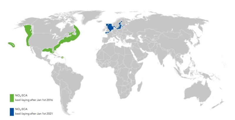
Emission Control Areas must comply with NOx “Tier III” emission limits which means that they must emit 80% less nitrous oxides than a “Tier I” complaint engine. Under these regulations, ships which are keel-laid after January 1st 2016 and operating in the United States/Canadian Emission Control Areas(ECAs) must comply with the new emission limits.
These emission limits are applicable for engines with an output power of more than 130kW installed on ships with more than 5,000GT
Tier III standards are expected to require dedicated NOx emission control technologies. These mainly consist of two options.
1) Using Liquified Natural Gas (LNG) as a fuel in engines, using lean burn technology.
e.g.- Win GD Engines-Winterthur Gas & Diesel Ltd. which burn LNG in their combustion chambers using a Low-Pressure LNG gas injection system for the reduction in NOx emissions.
2) Use of abatement technology such as various forms of water induction into the combustion process (with fuel, scavenging air(in-take air humidification), or in-cylinder), exhaust gas recirculation, or selective catalytic reduction.
This article throws light upon Selective Catalytic Reduction Reactors on Ships, it’s types, their basic working principle, components, its benefits, advantages and disadvantages.
Basic Working Principle

Selective Catalytic Reduction is a means of converting nitrous oxides in the exhaust with the help of a catalyst into diatomic nitrogen and water.
A reductant Anhydrous Ammonia (NH3), Aqueous Ammonia (Ammonium Hydroxide) or Urea (Carbamide) solution is added to a stream of exhaust gas and is adsorbed onto a catalyst. Carbon Dioxide (CO2) is a reaction product when urea is used as the reductant.
The chemical equation for the reaction using either anhydrous aqueous ammonia for the process is
4NO + 4NH3 + O2 = 4N2 + 6H2O
2NO2 + 4NH3 + O2 = 3N2 + 6H2O
NO + NO2 + 2NH3 = 2N2 + 3H2O
The reaction for urea instead of anhydrous or aqueous ammonia is
4NO + 2(NH2)2CO + O2 = 4N2 + 4H2O + 2CO2 (in presence of catalyst)
Selective Catalytic Reduction
This exhaust gas after-treatment technology has a NOx abatement capability Of more than 80%. The SCR concept involves injecting a Urea-Water solution into the exhaust gas stream in combination with a special catalyst unit.
The SCR is considered as an additional and independent exhaust treatment system and as such does not interfere with the basic engine design or combustion process.
The process diagram below gives a better understanding of the SCR system wherein the urea interacts with nitrous oxides present in the incoming exhaust gas, in the presence of a catalyst, converting it into free nitrogen and water vapour.
The Maritime Environmental Protection Committee (MEPC) At The IMO has published guidelines for the certification of selective catalytic reduction (SCR) systems, referred to the “SCR Guideline”, namely IMO Resolution MEPC.198(62).
According to their configurations, SCRs can Be Classified into 2 Types- They can be either installed between The Exhaust Gas Manifold & The Turbocharger or between The Turbocharger and The Exhaust Gas Boiler.
1) High-Pressure SCR
In the High-Pressure SCR, the reactor is placed before the turbocharger. A sufficient exhaust

gas temperature is to be maintained between 300 to 400 deg Celsius, which might be challenging when the engine is running at low loads and manoeuvring.
Therefore, for two-stroke engines, the most likely location of the SCR unit is before the turbocharger in order to expand the active range of SCR operation. This has little to no effect on the engine combustion process.
It is possible to run high-pressure SCRs on Heavy Fuel Oil.

2) Low-Pressure SCR
In Low-Pressure SCRs, the reactor is placed after the turbine. Pre-heating of the exhaust gas stream may be necessary in order to achieve a sufficient temperature at the reactor inlet for the catalytic reaction. Some power generation may be needed for preheating.

Components of an SCR
Dosing Unit
The dosing unit consists of a compact external dosing system having a urea-water solution tank. The tank size depends upon how often the vessel enters NOx Tier III areas and how often the SCR is put in use. Urea Tank capacities range from 4 to 10 cub metres/MW for larger engines.
The area for marine use is usually dissolved in water having a concentration of 32%-40%. Urea is a non-toxic odourless solution considered safe to transport and store at ambient temperature & pressure. However special caution is required in winter temperatures in order to avoid crystallization.
The dosing handling system provides the reducing agent (urea solution) based on the dosing demand signal provided by the SCR and Engine control and monitoring system.

Vaporizer/ Mixing Unit
The urea from the dosing system is metered and injected into the vaporizer or mixing unit. The injected reducing agent (urea) will vaporise and mix with the incoming exhaust gas.
The mixing unit is in line with the exhaust manifold of the engine and its pipes are designed & constructed after complex flow calculations & intensive testing, to ensure a good mixture of the urea solution & hot exhaust gases. The mixing unit is usually 2 to 6 meters long and 500mm in diameter, however, size may vary as per Engine size.

Injection tubes from the dosing unit penetrate the vaporizer from the bottom, the top of the vaporizer is equipped with an electronic enclosure having a NOx measurement sensor to monitor nitrous oxides in the exhaust gas and Backpressure sensor.
SCR Reactor Chamber
This is where the conversion of NOx in exhaust gas into nitrogen and water takes place in the presence of catalyst material. The SCR reactor contains cassettes of the catalyst substrate material. The substrate elements work in limited temperatures, if exhaust gas temperature is too high, the elements get destroyed.
If the temperature is too low, SCR efficiency is reduced. Catalyst element contains Vanadium Pentoxide (V2O5) which helps the reaction process of converting the urea and exhaust gas into nitrogen and water vapour. The SCR reactor volume is usually 1.5-3 cub metres/MW installed power.


Fuel Oil Quality and SCR technology
The sulphur content in fuel oil and consequent SO2 concentration in the exhaust gas is a critical parameter which has to be observed while operating SCR systems. Urea temperature is to be controlled according to sulphur content in fuel.
A high sulphur content in presence of a low exhaust gas temperature (in case of manoeuvring) will require a higher temperature of urea solution to be injected as a condensation of exhaust gas could result in corrosion and catalyst substrate damage. A lesser content of sulphur in fuel will allow a lesser temperature of urea solution to be injected.
Condensation of water vapour in the presence of sulphur in the exhaust gas during low load operations can cause the formation of solid ammonium bisulphate. Thus, the exhaust inlet temperature is to be kept high enough to avoid condensation of ammonium bisulphate onto catalyst substrate elements.
Condensation would severely affect NOx reduction performance and cause clogging, increasing backpressure due to soot formation in the reactor.

Soot Blowing Unit
To prevent contamination of the reactor elements, a soot blowing system is installed. Soot blowing is done using compressed air of 7 bar.
SCR Control Sensor Unit
NOx sensors measure the NOx concentration before the SCR reactor and the turbocharger.
The reactor chamber also contains outlet NOx sensors and outlet temperature sensors.

Venting System
The venting system vents the SCR reactor when the SCR is bypassed (i.e. when the engine is running in Tier-II mode) to avoid exhaust gas accumulation and soot formation in the reactor. The reactor is vented with Fresh Air during Tier II operation.
The Reactor Sealing Valve is used to seal the reactor during venting when the SCR is not in use.
Reactor Throttling Valve is located at the outlet of the reactor.
Reactor Bypass Valve is used to bypass the reactor for NOx Tier II operation or failure of the SCR.
The Cylinder Bypass Valve can be used while the engine runs at partial loads to bypass scavenge air towards the turbocharger to increase exhaust gas temperature.
The Cut-In Cut-Out settings of Auxiliary blowers are set slightly differently in case of engines fitted with SCRs. While cutting-in of auxiliary blowers at the time of reducing load, a slight delay is introduced so as to avoid a sudden drop in exhaust temperature.
Similarly, while cutting-out the auxiliary blowers, when engine load increases, the exhaust temperature tends to increase suddenly, to prevent this- the Cylinder Bypass Valve (CBV) opens first to gradually increase temperature, then the blowers cut out and the CBV later closes as per engine load.
Pros & Cons Of The SCR
To assure continuous NOx removal and avoid clogging, special considerations have to be observed with regard to exhaust temperatures.
Pros
● Tier III NOx compliance is achievable.
● Very efficient NOx removal for most engine loads (60-90%)
● SCRs have a widely growing reference base with over 300 installations
Cons
● Rather investment intensive
● Limited NOx removal at low engine loads
● In comparison to other solutions for NOx Tier III emissions, the use of urea requires the installation of urea tanks which may have to be replenished often (a costly affair)
● Can result in excess consumption of fuel (about 1%)
● Additional cost of Urea in ECA areas.

Maintenance
● Replacing NOx sensors- sensor life is approx. 2000hours
● Replacing the substrate catalyst elements in the SCR reactor (Lifetime-approx. 1000hours)
The lifetime of the catalyst elements strongly depends upon the sulphur content of the fuel. For NOx Tier III compliance, NOx efficiency is to verified once a year.
If NOx efficiency reduction < 70% all catalyst elements must be renewed as per manufacturer’s instructions.
● The Soot Blower consists of a compressed air bottle, soot blower diaphragm valves and pressure switches. All pressure hoses are to be checked and diaphragm valves to be maintained.
● The Dosing Unit consists of a urea solution tank, liquid filters, dosing pumps, nozzle assemblies, flowmeters, valves and pressure switches.
Weekly maintenance includes cleaning of filters, monthly includes inspection of injectors. Proper inspection and working of all individual components are to be checked every 6 months.
Benefits For The Ship Owner/Operator
Installing NOx Tier III-compliant technology has been beneficial beyond just achieving compliance with emissions regulations. Demonstrating a company’s commitment to ensuring sustainable operations has become increasingly important.
Some additional advantages include direct financial benefits, as major ports offer substantial discounts in harbour fees. One frequently used performance indicator for the environmental impact of shipping is the Environmental Shipping Index (ESI), which is used by major ports to calculate harbour fees.
Installing Tier III-compliant technology, instead of Tier II-compliant technology, adds approximately five points on the ESI scale.
For example, the following reductions in harbour fees for operating on Tier III are given by these ports:
Los Angeles: $2,500 per call (ESI higher than 50)
Hamburg: €1,500 per call (ESI higher than 50)
Rotterdam: 20% reduction for Tier III
Antwerp: 10% ESI higher than 31
Image credit: Cat Marine
Disclaimer :
The information contained in this website is for general information purposes only. While we endeavour to keep the information up to date and correct, we make no representations or warranties of any kind, express or implied, about the completeness, accuracy, reliability, suitability or availability with respect to the website or the information, products, services, or related graphics contained on the website for any purpose. Any reliance you place on such information is therefore strictly at your own risk.
In no event will we be liable for any loss or damage including without limitation, indirect or consequential loss or damage, or any loss or damage whatsoever arising from loss of data or profits arising out of, or in connection with, the use of this website.
Do you have info to share with us ? Suggest a correction
Disclaimer :
The information contained in this website is for general information purposes only. While we endeavour to keep the information up to date and correct, we make no representations or warranties of any kind, express or implied, about the completeness, accuracy, reliability, suitability or availability with respect to the website or the information, products, services, or related graphics contained on the website for any purpose. Any reliance you place on such information is therefore strictly at your own risk.
In no event will we be liable for any loss or damage including without limitation, indirect or consequential loss or damage, or any loss or damage whatsoever arising from loss of data or profits arising out of, or in connection with, the use of this website.
Latest Marine Technology Articles You Would Like:
- 10 Harmful Effects Of Impure Air On Ship’s Machinery

- 10 Important Things to Check While Starting Fuel Oil Purifier on Ships
- 10 Noteworthy LNG-Powered Vessels
- 10 Points for Efficient Turbocharger Operation On Ships
- 10 Practical Tips to Handle Engine Room Pumps
- 10 Precautions to Take Before Operating Controllable Pitch Propeller (CPP) on Ships


Subscribe To Our Newsletters
By subscribing, you agree to our Privacy Policy and may receive occasional deal communications; you can unsubscribe anytime.