

Shipbuilding Process : Finalising And Launching The Ship
The previous article of this series dealt with methods of rolling and bending of plates and sections of the shipbuilding process. We then had an overview of how sub-assemblies, assemblies are fabricated in the prefabrication shop. These are then welded to form units, which are erected as per a pre-decided welding sequence.
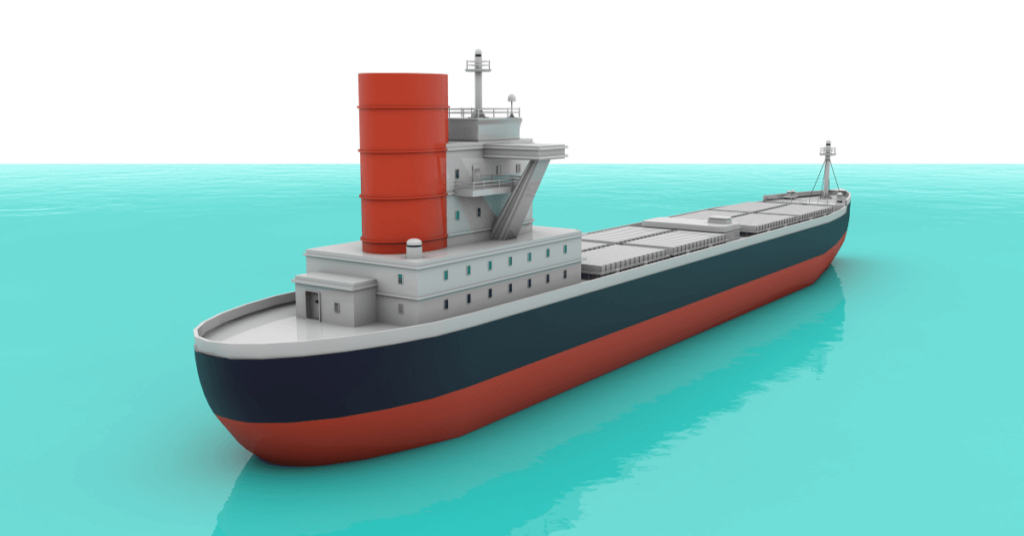
Once all the units or blocks are erected, they are ready to be welded as per a pre-decided sequence, for the entire ship to be erected. We take a step back and start by understanding how a ship is divided into blocks, as shown in Figure 1.
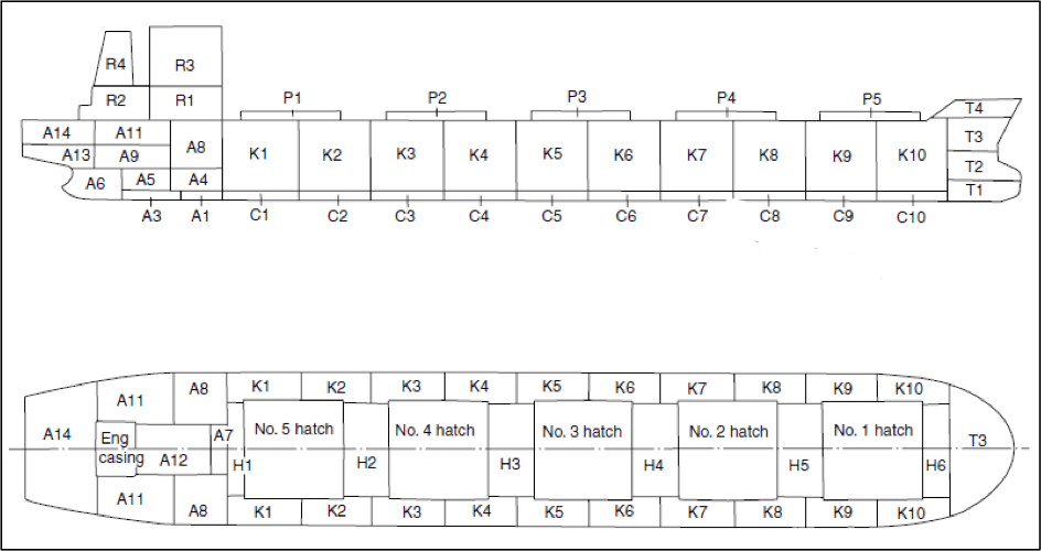
The above figure shows the division of a bulk carrier into blocks. It is important to understand that a block may not be of full width of the ship, and the size of a block depends on the capacity and the carnage facilities in the shipyard.
During the shipbuilding process, each ship block is brought to the building dock, where they are erected with cranes, as per the welding sequence. After each erection, welding is carried out on block joints. Alignment of blocks is a very important factor determining the productivity of the shipyard, and quality assurance measures are taken to ensure proper alignment. Improvements in alignment have been made by use of proper jigs for curved shell panels, proper welding techniques that have lower heat input, and by the use of laser alignment tools.
A shipbuilding berth is a dock-like structure with flooring level below the mean sea level. When all the blocks are erected and welded, the dock is then flooded and the ship is floated out to the outfitting jetty. However, many shipyards in which the level of flooring in the building dock is above the mean sea level, the ship is made waterborne by using specialised launching techniques, which we will discuss later in the article.
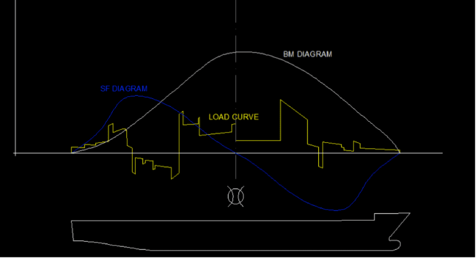
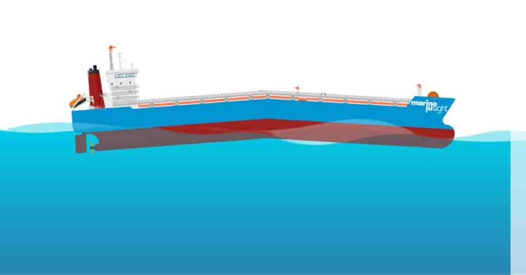
In some shipyards erection of blocks, in case of very large bulkers and tankers, is carried out directly in afloat condition. This is practised in case the size of the ship exceeds the capacity of the building berth or in cases where two halves of a ship are built at separate berths, and are floated. Then the two sections are pulled together using tackles, and their aligned to fine precision by means of optical measurement devices. Usually, at the joint (for example, the joint between K4 and K5 in Figure 1), caissons are welded to both the halves. Initially the caissons are pumped dry. Before welding of both the halves, the caissons are ballasted so as to attain the required draft for both the halves to be aligned for vertical welding. Since the joint is at the midship, ballasting the caissons would result in sagging of the hull girder. So the fore-peak and aft-peak tanks are ballasted to offset the effects of sagging. After the welding is carried out at the joint, it is X-Ray tested for any weld defects. This welding joint is one of the most vital weld joints in the entire ship, as it is located in the vicinity of the midship (and midship being the region subjected to maximum bending moment. See Figure 2).
Launching
Many big shipyards now construct ships on building docks, which are then flooded, and the ship is towed out to the outfit basin by a tug. But most shipyards still follow the traditional process of launching a ship. Today, launching methods have become safer and more proactive in approach as computer programs help the engineers to estimate the load on the ship during launch.
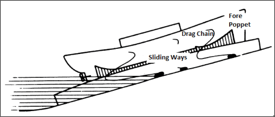
When the ship is built, the entire load of the ship is taken by the keel blocks. Once ready for launch, the forward and aft cradles are constructed and welded to the hull. Now, the weight is ready to be shifted from the keel blocks to the cradles. The ship, along with the entire cradle structure is made to slide along the slideway, to the adjacent water body, where the load is balanced by the buoyancy, a process which we will understand in detail a little later.
The ship can be launched end on, stern first (that is, the stern of the ship is made waterborne before the forward part), or sideways. Usually, end launching is preferred as it ensures better load distribution on the slipway and the cradle. However, in case of shipyards where the extent of the adjacent waterbody is insufficient to accommodate the length of the ship, side launching is preferred.
The ship is tied to the shore by means of drag chains. The length of the chains are so designed such that they are loose before launch, and taut enough after launch to restrict the ship from hitting the opposite bank.
Outfitting
After launching, the ship is towed to the outfit basin. The outfit basin of a shipyard is usually located in proximity to the engineering and machinery workshops of the yard where the outfit items are fabricated.
As we discussed in previous parts, larger shipyards prefer advanced outfitting, hence, almost 95 percent of total outfit work is completed during the building stage itself. The remaining minor outfit items are fitted at the outfit basin. However, in smaller and standard shipyards where advanced outfitting is not feasible, complete outfitting is carried out at the outfit basin.
Sea Trials
Once all the construction and outfitting work is completed, the sea trials are carried out by the shipyard authority, in the presence of a designated representative of the ship’s owner. Some tests include Speed Trials, Turning circle test, Crash stop test, Zig-zag or Kempf’s Overshoot maneuver, Spiral Maneuver, Engine trials, and Astern test.
After the results of the sea trials are studied and found acceptable by both, the owner and the shipbuilder (as per specifications mentioned in the contract), the ship is delivered to the client. If the results do not satisfy the requirements as per the contract, the shipbuilder is given a grace period to make required modifications, after which, sea trials are carried out again. If the ship is not delivered with satisfactory results after the lapse of grace period, the shipbuilder is bound to pay penalties to the owner, as per the contract.
Overview
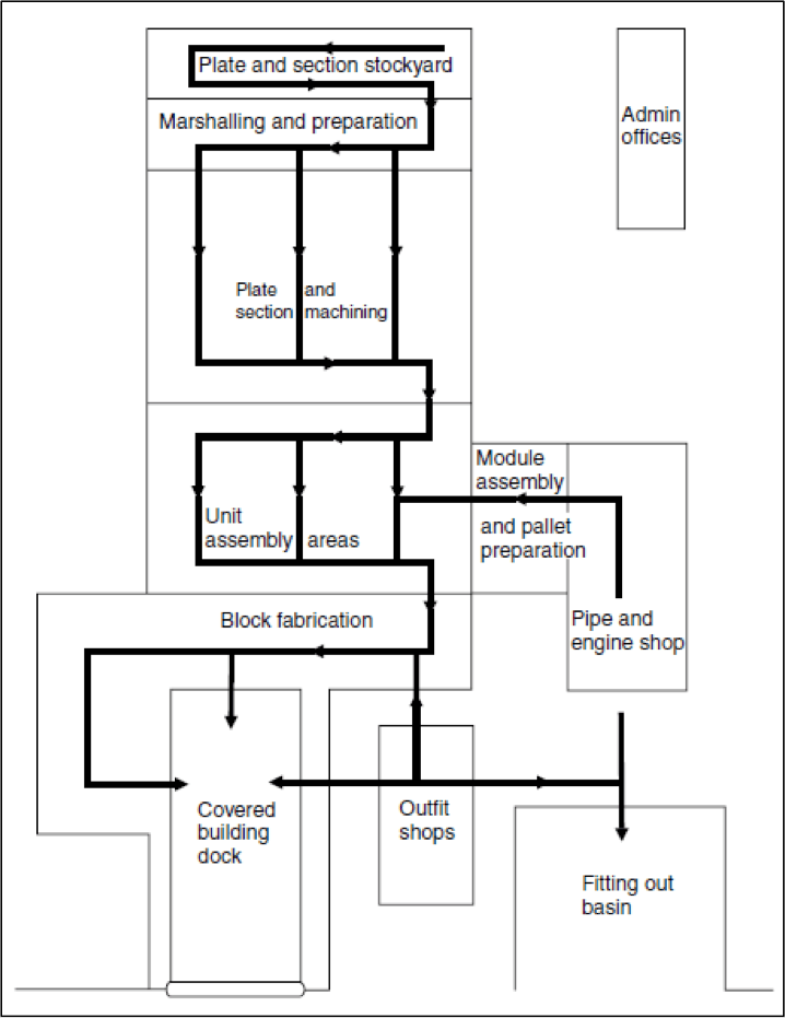
We began this series of articles with an aim to understand the entire shipbuilding process and the flow of material from the stockyard to the end product. A reader acquainted with the first two parts would know that we have taken a different approach in understanding the entire process. Rather than first having an aerial view of the shipbuilding process, we discussed each process in detail, as per the sequence followed in the industry. At this stage, having understood in detail, about every step in the shipbuilding process, it would be easier for the reader to now have an overview of the process flow in a shipyard. It is this process flow that is the deciding factor in the layout of every shipyard, as shown in Figure 3. Have a look at this layout and try to understand each component, their use, and try to reason out why a particular component is located where it is.
Do you have info to share with us ? Suggest a correction


Latest Naval Arch Articles You Would Like:


Subscribe To Our Newsletters
By subscribing, you agree to our Privacy Policy and may receive occasional deal communications; you can unsubscribe anytime.
Web Stories

Dear sir
I have one project that is in turkey to make ship rail on sea and fabrication And structural work in the sea
Need suggestions and party who can perform this mega project