

Understanding Capacity Control in Ship’s Air Conditioning and Refrigeration System
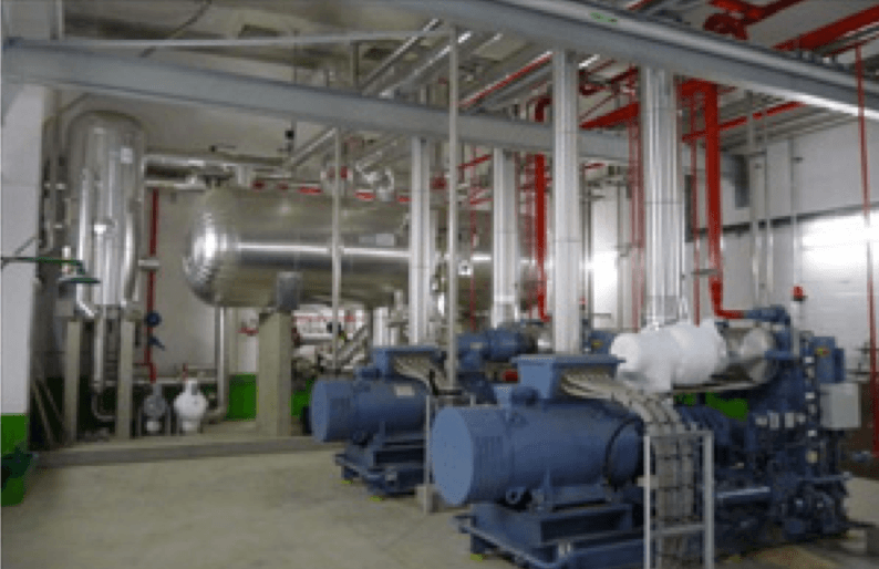
Ship’s air conditioning and refrigeration system help in lowering room temperature and in keeping perishable food items and refrigerated cargo at a desirable temperature.
As discussed in our article about basics of refrigeration plant – Construction and Working of Ships Refrigeration plant on ships, the reefer, and air conditioning systems are installed to handle fluctuating loads i.e. they are responsible for maintaining the low temperature of several rooms or cargo holds at the same time.
The efficiency of the refer plant depends on its ability to keep different rooms or holds at a different temperature. Each room will have its own load demand hence the refrigeration plant’s output has to be controlled to achieve required cooling.
What is Capacity Control?
Capacity control of a refrigeration plant can be defined as a system which monitors and controls the output of the plant as per the load on demand. As the load (temperature) of one room is reached to its required temperature, there will be no more need of the refrigerant for cooling. Hence, the solenoid valve supplying refrigerant to that room will shut.
The refrigeration compressor consists of different units working in parallel to cope up with the load. As the load decreases, the capacity control system cut off one or more units (depending upon the load) and maintains the efficiency of the plant by reducing stresses on different parts.
The simplest forms of controlling the room temperature are:
- Using Variable Speed Motor (Normally used on small AC units)
- Controlling on-off cycling of the compressor
- Using Cylinder unloading method of keeping the suction valve in open position. This is accomplished by introducing a capacity controller valve in the compressor which is operated by lube oil pressure (hydraulic type) or by sing a solenoid operated control valves
By using the first 2 methods, following Mechanical problems are experienced:
- Motor overheating: An excessively high switching frequency will cause excessive motor heating
- Bearing damage: During the startup phase, the oil pressure is low and bearing lubrication is not optimal leading to reduction of shelf life of bearings and connected parts
- Oil return in intermittent mode: More oil enters the refrigerant cycle during startup than during continuous operation; frequent switching does not provide sufficient oil return
Capacity Control Valve – Lube oil operated
Components and Working of Capacity control valve system
- Compressor lube oil pump supply
- Capacity control valve
- Capacity control regulating valve
- Un-loader assembly
The compressor lube oil pump supplies oil to all the bearings, and one connection is provided to the capacity control valve.
The capacity control valve is provided with high-pressure oil from the lube oil supply pump of the compressor. This valve had several grooves bored into its periphery and connected to the unloader mechanism of different units.
A spring piston is provided which controls the spreading of high-pressure oil supply into the bore chamber. The spring piston is pressed by the oil supplied through an orifice which pushes the piston and aligns the un-loader holes, providing high-pressure oil to the unloader unit.
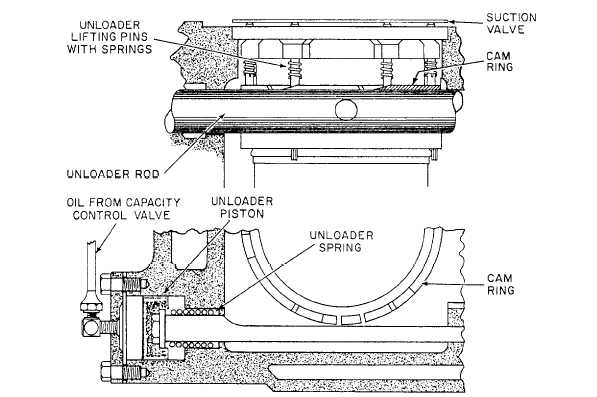
The un-loader assembly comprises a un-loader piston held by a spring. The un-loader piston is connected to a rotating cam ring having lifting pins attached to the suction valve. The lifting pins always act on the suction valve i.e. un-loading the unit at stop condition.
When the bores on control valve align with the unloader bores, oil will pass and press the un-loader piston rotating the cam and releasing the un loader pins from the suction valve.
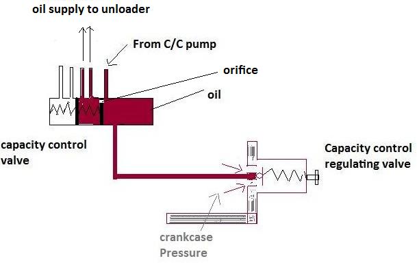
The capacity control regulating valve is responsible for controlling the pressure (opening and closing of capacity control valve ports with un-loader ports). Its one end is connected to the crankcase and another end to the capacity control valve.
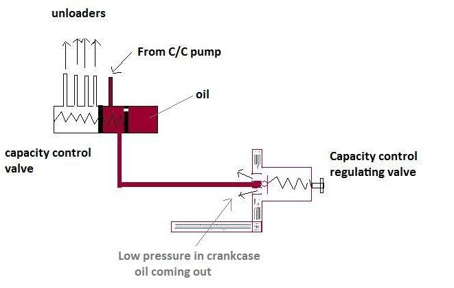
As the pressure in the crankcase drops due to a reduction in load, oil in the capacity control valve is drained into the crank case leading to the closing of un-loader ports, lifting of the suction valve, and cutting of the cylinder unit. This likewise means that all such cylinders are unloaded at start up releasing the unnecessary load on the motor during the starting period.
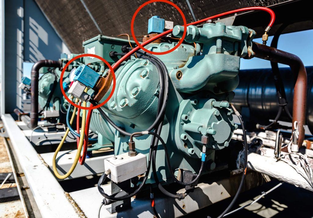
Capacity control valve- Solenoid operated
In this type, solenoid valves are used in conjunction with servo valve to operate the opening and closing of the suction valve. It is fitted on top of the cylinder (near suction valve). During energized position, the solenoid closes the access between the two cylinders or stages in the compressor, by keep the suction valve open and bypassing the hot discharge gas directly to the suction line making the pressure of the unit as zero bar, and reducing the capacity of the compressor by half.
With the solenoid valve de-energized, the gas ports in the valve plate and cylinder head are open.
The only disadvantage of this type is that the spring in the solenoid valve may malfunction and its operation is affected by high variation in temperatures.
Do you have info to share with us ? Suggest a correction

About Author
An ardent sailor and a techie, Anish Wankhede has voyaged on a number of ships as a marine engineer officer. He loves multitasking, networking, and troubleshooting. He is the one behind the unique creativity and aesthetics at Marine Insight.

Subscribe To Our Newsletters
By subscribing, you agree to our Privacy Policy and may receive occasional deal communications; you can unsubscribe anytime.
I’m air conditioner. Plant operator
sir
iam aircondition working. I can.t all type airconditio work. So. Iam. Coming sir.
1. Should the maximum pressure test exceed 90%MWP?
2. Can a recovered refrigerant from a unit be used again for a different if both units have the same refrigerant type.?
What is the difference between the main air compressor unloader valve and refrigeration compressor unloader valve? Do they serve the same purpose?
@Ye Lin: Main air compressor unloader comes in action during the starting and stopping to avoid overloading to the motor
The reefer compressor unloader is used to cut in and cut out units (for the multistage compressor), as per the load requirement of the rooms.