

Hull Corrosion And Impressed Current Cathodic Protection (ICCP) On Ships – Construction And Working
Ships are often exposed to very harsh marine environments. Due to the environment in which they operate, the ship’s hull is often vulnerable to environmental corrosion.
The corrosivity of seawater in regards to general corrosion on steel increases with increasing temperature, oxygen content, water velocity, the content of corrosive contaminants, eroding particles, and conductivity. The seawater containing salt forms a perfect electrolyte with the ship’s hull, fully made up of iron (mild steel), to form a galvanic cell.

What is a Galvanic cell and why does the ship’s hull corrode?
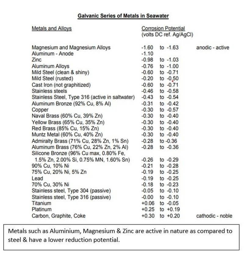
When 2 dissimilar metals are in contact with each other in the presence of a corrosive medium (electrolyte), the more active metal in the galvanic series acts as an anode and undergoes corrosion. This means, in a galvanic series of metals, the more active metal acts as anode and undergoes corrosion and the less active metal acts as a cathode and stays protected.
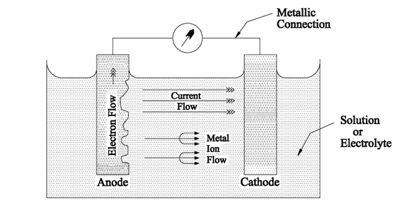
If these two metals are placed in seawater and are in direct electrical contact, a current will pass through the electrolyte from the more active metal (anode) onto the least active metal(cathode). This electrical current is referred to as Corrosion Current and is nothing but a metal ion and electron transfer process from the anode, which dissolves and passes into the solution. This simple cell where the corrosion process takes place is called a Galvanic Cell.
So how does Corrosion take place on ships?
Ships are made of steel; whose main component is iron. Iron is an electrochemically positive element and has a tendency to give up electrons to become free ions.
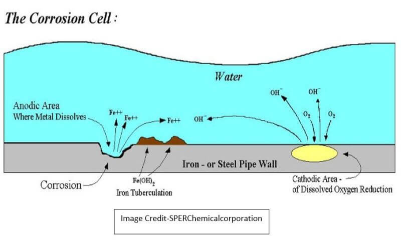
1) Anodic Reaction that takes place is 2Fe → 2Fe++ + 4e-
2) Seawater is composed of oxygen and hydrogen, and it produces electrochemically negative hydroxyl ions H2 O + O2 + 4 e- → 4 (OH)- which can accept the electrons given by Iron.
3) The Iron ions combine with the hydroxyl ions in seawater to form Ferrous Hydroxide. 2 Fe++ +2 (OH)- → 2 Fe (OH)2. This is called the Oxidation of Iron.
4) This Ferrous Hydroxide in the presence of excess oxygen in water is oxidized to form Ferric Oxide & water, which we call Rust. 2 Fe (OH)2 + O2 → Fe2 O3 + 2 H 2 O (Rust)
The heterogeneity of mild steel in the hull of the ship, along with factors such as non- uniformity of hull plate, thickness, paint thickness and quality, variations in the ship structure welding seams, dissimilar metals and oxygen content in the seawater combine to cause areas in the hull to work cathodes and anodes and thereby forming a galvanic cell.
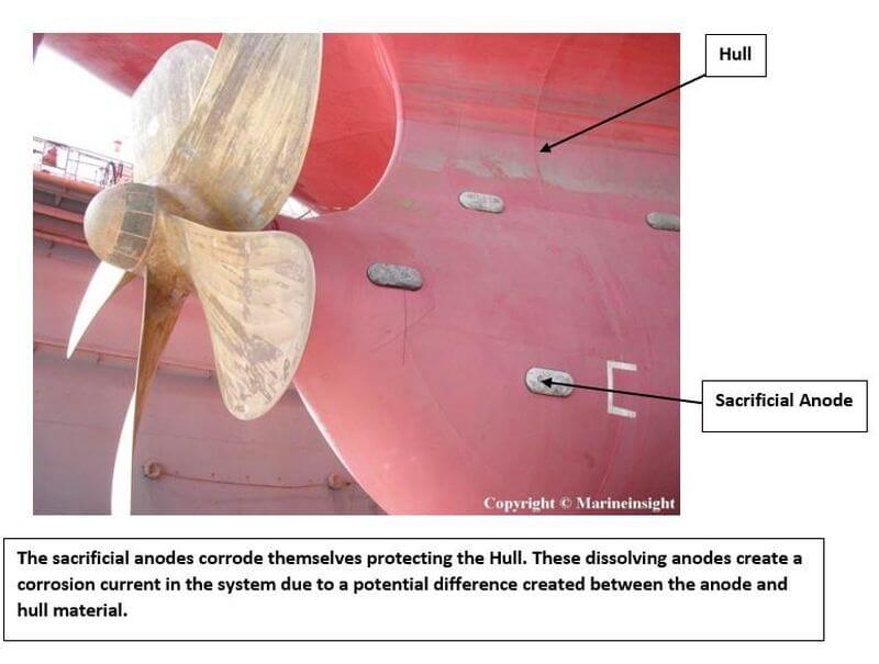
With the galvanic series, we now know that a more active metal(anode) can corrode in place of the lesser active metal (cathode). By coupling the ship’s structure with a more active metal such as zinc or magnesium, a galvanic cell is created in which the active metal working as an anode provides a flux of electrons to the structure which then becomes the cathode. The cathode is protected and the anode progressively gets dissolved which is hence called a sacrificial anode.
Elements such as Zinc, Aluminium, Magnesium or their alloys are used as a sacrificial anode to protect the parent element like Iron or Steel which forms the cathode. However, these sacrificial anodes do have some disadvantages such as increased maintenance due to replacement every 5 years, Increased Hull Resistance and no proper means to detect whether the anodes are functioning properly.
The Need For ICCP
We now know from the galvanic cell and the sacrificial anodes, that a potential difference between 2 electrodes is required for corrosion currents to occur. These corrosion currents dissolve the anode in the electrolyte.
But in the absence of a potential difference within the ship’s hull, the corrosion current will be at a minimum and corrosion will not take place.
THIS IS WHAT THE ICCP DOES. IT MAKES THE HULL TO REMAIN ALWAYS CATHODE by keeping the Potential difference to a minimum and introducing a current opposite to the natural corrosion current, thereby protecting the anode and avoiding corrosion.
Impressed Current Cathodic Protection
Impressed Current Cathodic Protection Systems are the technologically advanced and long-term solution to corrosion problems and is regarded as a superior alternative to sacrificial anode systems.
In the ICCP, the metal to be protected is connected to an insoluble anode and the current is passed using a DC source opposite to the corrosion current, so that the corroding metal gets
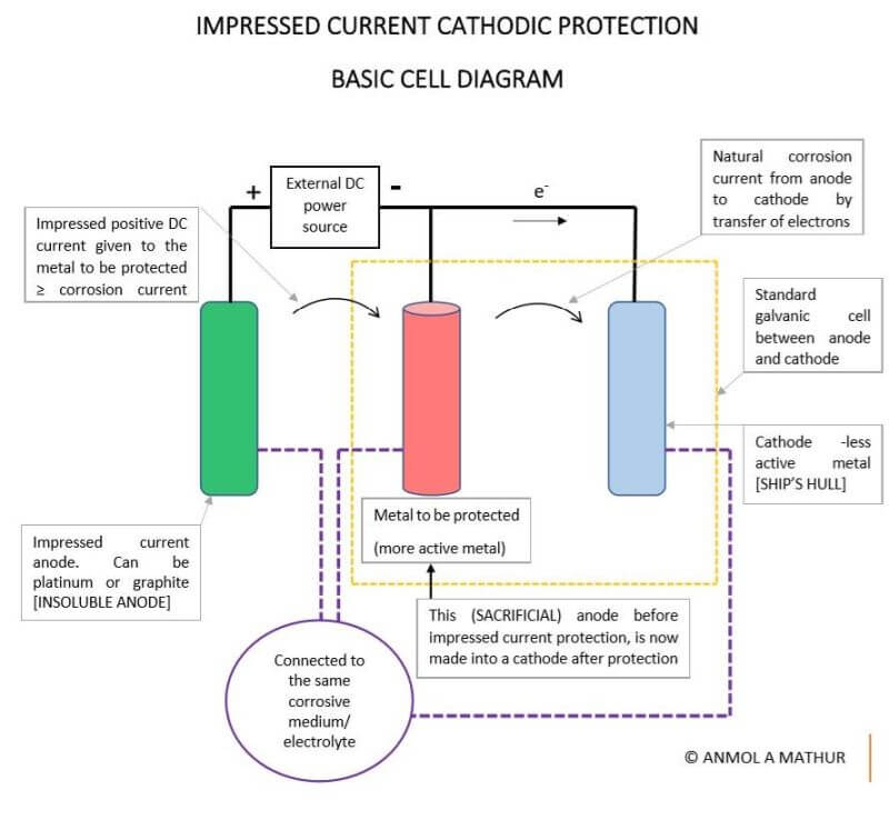
converted from anode to cathode and is protected from corrosion. This insoluble anode can be either platinum, platinized titanium or any other inert elements.
The above diagram is a similar galvanic cell of an anode (more active metal) and a cathode (less active metal) with some modifications. Here, an impressed current anode that is insoluble is added to the system.
Under normal circumstances, without the insoluble anode, a corrosion current is set up which corrodes the anode, however, in this case, we pass a DC current opposite to the natural corrosion current between the anode and cathode.
This DC current has to be equal to or slightly greater than the natural corrosion current so that the anode is now protected and does not corrode.
The same principle is applied to ships.
Here, a contact point is taken on the hull of the ship and is connected to a reference electrode. This reference electrode is a completely passive insoluble metal. The reference electrode measures the natural corrosion current which is nothing but the potential difference between the hull and this reference cell.
We need to measure this corrosion current in the hull, so that we supply a DC current that is either equal to or slightly greater than it (in the opposite direction) to the Impressed current anode.
This, in turn, supplies A PROTECTING CURRENT to the Hull of the ship, making the hull a cathode protected from corrosion.
The ICCP Operation & its Components
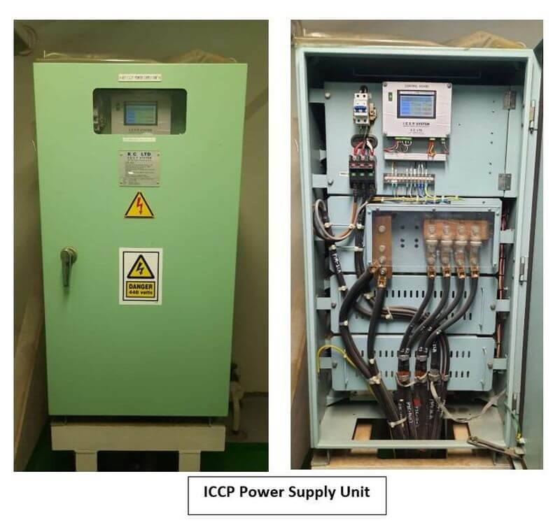
1) DC 24V Output Power supply unit & Control Panel
The DC Power supply may include a rectifier unit converting 440V AC supply to DC current.
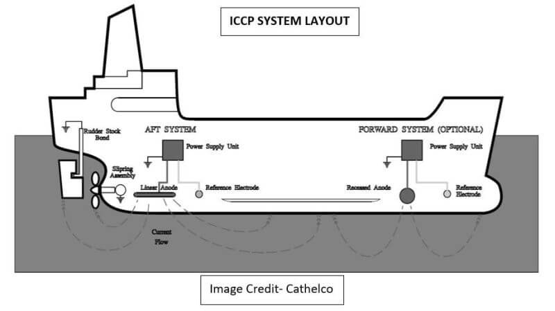
Larger ships usually have 2 power supply units each in the Forward and the Aft. The Power Supply Unit is also known as the Quantum ICCP panel and it contains a network of thyristors and PCBs which monitor voltage and current parameters from the reference cells and accordingly sends signals to the impressed current anodes. These power supply units have a master-slave configuration between forward and aft units and performance can be monitored from the ECR monitor panel. The control panel is incorporated with alarms for abnormal readings.
2) Impressed Current Anodes
The impressed current anodes are usually made up of strong insoluble materials like titanium. They may be disc or stripe-shaped. Either 2 or 4 units are placed symmetrically forward and aft of the vessel.
The anodes are welded on doubler plates onto the hull surface so as to be completely flush to the outside hull plate. This anode material serves only as a source of electrons to the hull and is not consumed in providing this protective current.
3) Zinc Reference Cell
The electrical potential is monitored by reference electrode assembly which is fitted port and starboard between the anodes where the lowest possible potential is likely to occur so as to detect the slightest of corrosion currents between the hull and seawater. This reading is fed back to the control panel which automatically adjusts the impressed current anode output.
They are connected through cable lugs & gaskets and are bolted through a cofferdam body onto the hull surface. These Zinc reference cells are highly stable in nature and give a steady reference in which hull and sea potentials can be measured along with small current flows in the system. These electrodes are completely diver changeable.
The video above gives a clearer picture of the ICCP working onboard.
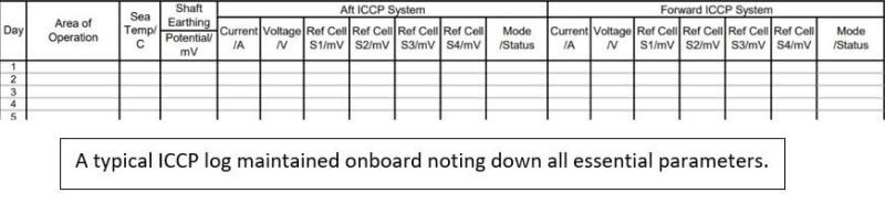
4) Remote Monitoring Panel
A remote monitoring panel in the engine control room is provided where ICCP parameters are monitored and logged down daily. It is to be made sure that the ICCP Power source is switched off when the vessel is berthing. Or else there is a chance of the ship and shore ICCP system currents to interact with each other, causing hull paint damage. Excess of impressed current into the hull surface can lead to paint peeling off.
5) Rudder Bonding Cable
To enable the rudder to receive corrosive protection through the ICCP, a flexible Rubber bonding cable is used with one end attached to the top of the rudder stock and the other end to the Hull Structure using cable lugs or eye plates. This forms a dedicated electrical bond.
6) Propeller Shaft Grounding assembly with Shaft hull mv voltmeter
Even on ships fitted with the ICCP, propeller shaft bearings are vulnerable to corrosion due to Spark Erosion. This is because the rotating propeller shaft is electrically insulated from the hull by the lubricating oil film in the bearings and the use of non-metallic bearings in the tail shaft. Due to this insulation created, an electrical potential is developed between the shaft and the hull which can cause heavy currents to flow in the bearing.
Heavy currents can also flow into the main bearings and thrust bearing and cause pitting marks leading to Main Engine Damage.
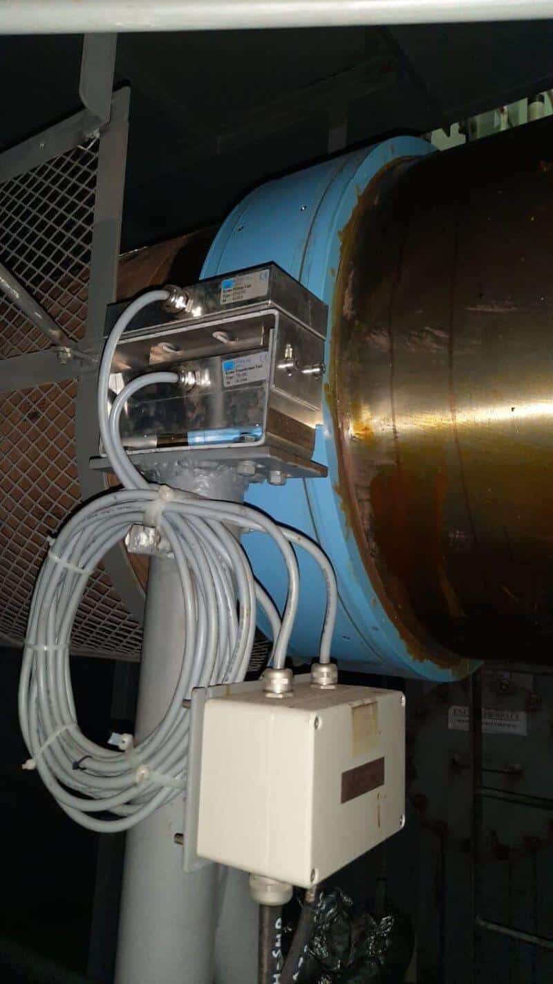
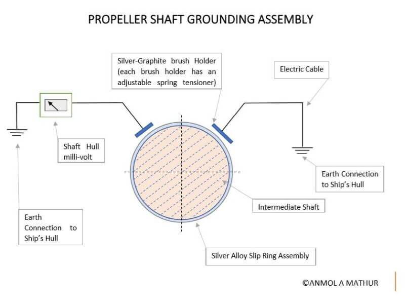
This problem is eliminated by earthing the propeller shaft to the hull with the help of a slip ring and contact brush assembly.
The shaft earthing assembly consists of a pair of high silver content/graphite compound brushes mounted in a brush holder, running on a copper slip ring with a solid silver alloy metal band inlay track.
The silver alloy earthing assembly provides excellent electrical continuity.
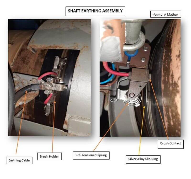
The silver alloyed Shaft slip Ring is supplied as a set of 2 halves along with a clamping arrangement so as to promote easy installation.
A compact millivoltmeter is installed to monitor the potential between the shaft and the hull and verify the effectiveness of the system. The meter is located in a convenient position for monitoring by the crew.
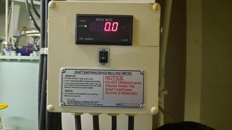
A reading of less than 50mV is considered favourable.
Fresh Water Passage
When a ship moves from Sea Water to Fresh Water, its electrical conductivity reduces and its resistivity increases. Because of reduced conductivity, the reference cell will not be able to detect a potential difference. At this time, it is important to limit the output protective current from the impressed current anodes.
During Fresh Water Passage, the automatic control in the Power Supply Unit of the ICCP will increase its rectified voltage to a maximum so as to limit the impressed current and avoid over-protection and save the hull.
At terminals, the Ship’s ICCP if switched ON, will try to protect the jetty as well thereby increasing the current in the system, This can lead to an overload. Hence the ICCP power source is always switched off in Port.
Hope this clarifies most doubts about the Impressed Current Cathodic System. The ICCP being very underrated machinery is often overlooked in the engine room and is overhauled and inspected usually in Dry Dock.
However, this is preferred by most Ship Owners due to it helping in reducing fuel consumption, increasing ship speed due to reduced hull resistance and maintaining hull-metal quality for longer intervals of time thereby increasing maintenance intervals and cost-effectiveness.
Have any doubts?
Feel free to ask in the comment below
Disclaimer: The authors’ views expressed in this article do not necessarily reflect the views of Marine Insight. Data and charts, if used, in the article have been sourced from available information and have not been authenticated by any statutory authority. The author and Marine Insight do not claim it to be accurate nor accept any responsibility for the same. The views constitute only the opinions and do not constitute any guidelines or recommendations on any course of action to be followed by the reader.
Do you have info to share with us ? Suggest a correction
Latest Marine Technology Articles You Would Like:
- 10 Harmful Effects Of Impure Air On Ship’s Machinery

- 10 Important Things to Check While Starting Fuel Oil Purifier on Ships
- 10 Noteworthy LNG-Powered Vessels
- 10 Points for Efficient Turbocharger Operation On Ships
- 10 Practical Tips to Handle Engine Room Pumps
- 10 Precautions to Take Before Operating Controllable Pitch Propeller (CPP) on Ships


Subscribe To Our Newsletters
By subscribing, you agree to our Privacy Policy and may receive occasional deal communications; you can unsubscribe anytime.
Web Stories


Nice understanding how a ICCP works. regards
Hello Anmol
I found the content on your page the most clear practical and theoretial combination on the internet. It explains this from an academic and a practical engineering standpoint. I used my understanding of the subject from your page to write a part of an extended essay for my IB exam.
Many thanks
What is the problems which we are facing with iccp system
Hello Anmol
I have witnessed corrosion in CuNiFe pipework and also Bronze filter housings on 3 different vessels that would not normally occur in a short period of service (12 months) could this be caused by IPPC? I nkow the CuNiFe relies on a natural organic coating building up on the wetted face to act as a barrier, the ICCP system removes this barrier causing the pipe to corrode internally, I do not know how IPPC affects Bronze but I have seen what looks like electrical errosion.
Wow, what a content and a helarious way of explanation for each and every aspect regarding ICCP! Keep it up, much much appericiated.
There will be high dc current,,but also there are passenger in ship why they don’t get shock ????
The ICCP is an active system which prevents electrolytic corrosion between the propeller & ship’s steel by releasing a low voltage but high current into the water adjacent the ship.
Good article. I have a daught to get clarify.
My question is,
Is it required to switch off the ICCP system when the ship at pier always. If it is so, how the hull will be protected during harbour period?
Waiting for reply
Thank you
How reference electrode measure the potential difference??
A reference electrode is an electrode that has a stable electrode potential. Voltages and potentials arise between an electron conductor (electrode) and an ion conductor (electrolyte) as soon as they are brought into contact with each other. Charges are exchanged until the system is balanced
Today ships DC current is going high more than 150 amp DC and breaker is tripping,giving alarm iccp abnormal….I tried to adjust the current at minimum but it’s not working….can you please let me know the reason why it’s happening
It is likely that the high DC current and tripping of the breaker is caused by a problem with the ship’s integrated control and communication system (ICCS) or the current control system.