

Marine Air Compressor Maintenance – Things You Must Know About
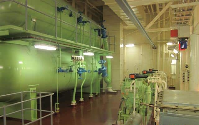
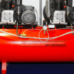
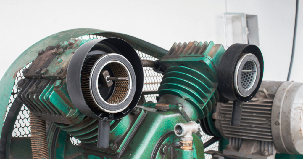
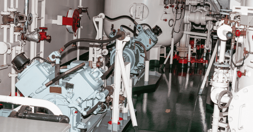
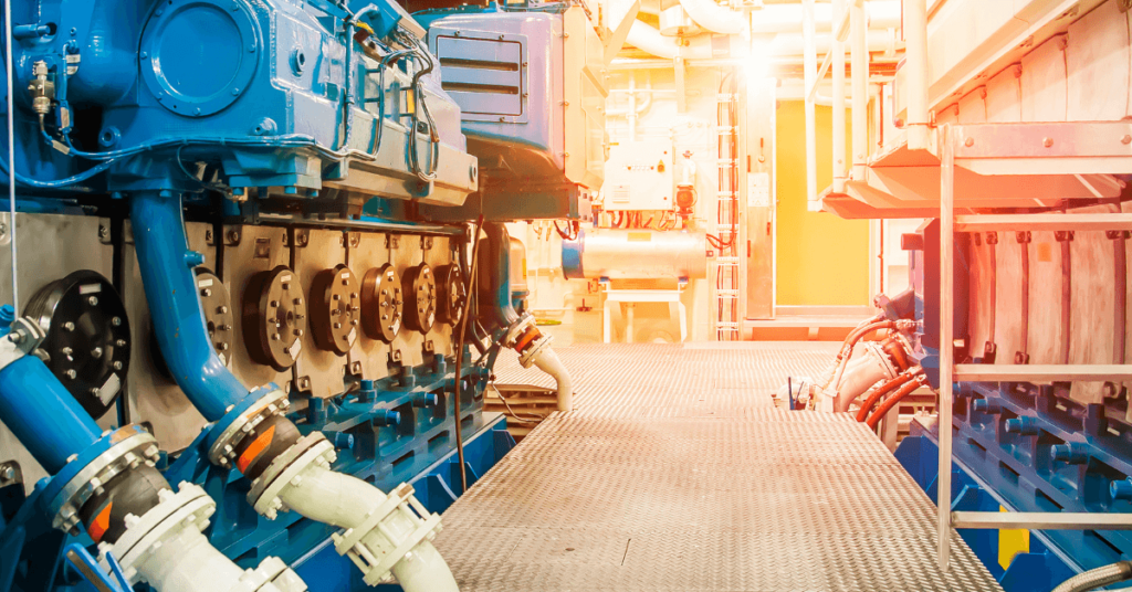
Marine air compressors are used to start large slow speed and medium-speed marine diesel engines, and therefore are an integral part of engine room on-board.
Generally, there are two compressors onboard a ship ( can be more than two depending upon the requirement of the vessel.)
The two compressors fill up the air receivers, which should have total capacity such that the engine can start 12 times ahead and astern without replenishment of the receivers. This capacity is limited to 6 times if it’s a unidirectional engine.
Each of the air receivers is fitted with a relief valve, which will limit the pressure rise to 10% of the maximum design pressure of the receiver.
Related Reading: Basics of air compressor on ship
Also, the outlet of the relief valves should be outside the engine room so that it doesn’t contribute in case there is a fire near the air receiver.
Usually, air compressors onboard are capable enough to charge both the air receivers from zero to full in one hour.
The air compressors are fitted with several safety devices as well such as relief valves on each stage which limit the pressure rise to 10% of the maximum working pressure.
The delivery side is fitted with a high-temperature switch which cuts off the compressor at a specified temperature or a fusible plug which may melt at 121 degrees centigrade.
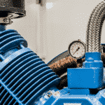
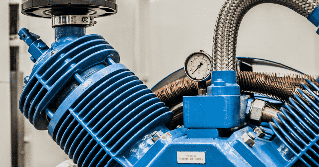
Performance of the marine air compressor is taken at the end of every month to ascertain the working capacity of the compressor.
The performance report includes the delivery air temperature, cooling water inlet and outlet temperatures, lube oil pressure and discharge pressures of each stage of the compressor.
Related Reading: Efficiency Of Air Compressor
The compressor is generally started in an unloaded condition so that minimum current is drawn by the motor and the bearings are devoid of oil.
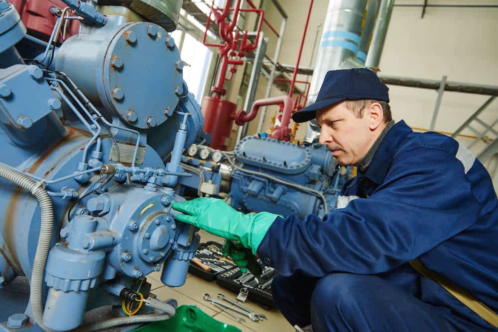
Maintenance jobs carried out on the main air compressor depending on the running hours of the compressor and all these jobs are mentioned in the maintenance manual of the compressor.
- The planned maintenance system devised by the company must be strictly followed else there can be a severe breakdown
- To avoid breakdowns in the main air compressor, the following maintenance must be considered
- Daily morning and evening rounds including checking of lube oil level, discharge pressures of various stages, discharge temperature and running time of the compressor.
- When an engineer takes over, he/she must first take note of all the maintenance jobs that might be due in his/her contract, and take spare part inventory and order the spares, if required with the help of Chief Engineer.
- The engineer must also note the torques required for tightening various bolts, screws and nuts on the main air compressor.
- The testing of air compressor alarms must be carried out as per the PMS, which generally demands the alarms to be tested once every three months.
- One of the most important things in the main air compressor is the bumping clearance of the compressor, which will be discussed later in the compressor maintenance.
- As a basic thumb rule, the main air compressor should run for 3-4 hours every day on an MR tanker. If the running hours exceed this duration, then the required checks must be carried out.
VOLUMETRIC EFFICIENCY OF AN AIR COMPRESSOR
The volumetric efficiency of an air compressor is defined as the ratio of the volume of air discharged by the compressor as free air and the swept volume of the LP piston, whereas free air is defined as the air at atmospheric pressure and 15 degrees centigrade.
Related Reading: Starting and stopping procedure of air compressor
BUSTING THE MYTH ABOUT BUMPING CLEARANCE
Well, you might wonder about Bumping Clearance being marked in bold, here’s the deal:
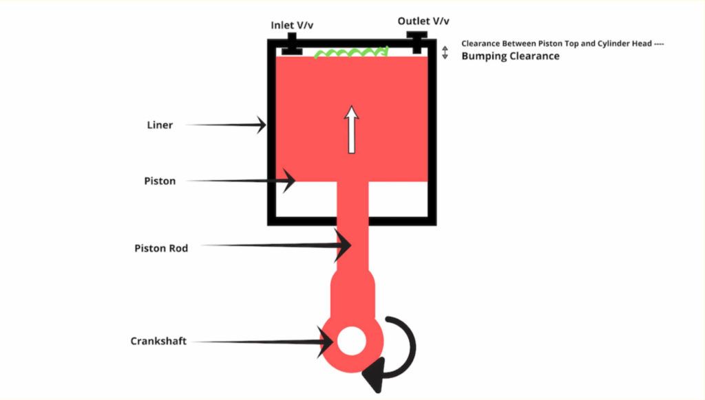
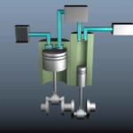
Bumping clearance is the top clearance in the main air compressor between the top of the piston and the cylinder head when the piston is at TDC.
This clearance is determined by the cylinder head gasket which should be of the correct size and indeed should be a genuine spare.
Related Reading: Top 5 Air Compressor Problems Marine Engineers Must Know
Bumping clearance is important as it relates to the volumetric efficiency of the compressor.
When the bumping clearance of the compressor is large then the clearance volume is big enough to accommodate a large volume of air when the piston is at the end of its stroke.
When the piston moves downwards, then a large amount of suction stroke becomes ineffective as the suction will happen only when the cylinder pressure falls below the atmospheric pressure.
Hence the piston stroke is wasted by expanding a large amount of air that has accommodated in the clearance volume due to a large bumping clearance.
HOW TO CHECK THE BUMPING CLEARANCE?
Generally, the bumping clearance of the compressor is fixed by the thickness of the cylinder head gasket used by the manufacturer but it could be measured by a lead ball placed between the top of the piston, assembling the compressor with the manufacturer recommended cylinder head gasket and taking the piston back to the top dead centre.
The ball will compress and then can eventually be measured by a micrometre. It is generally in the range of 1.2 mm to 1.8 mm.
FREQUENCY: 3000 RUNNING HOURS OR DEPENDING ON THE PERFORMANCE.
HOW TO ADJUST THE BUMPING CLEARANCE?
Bumping clearance could be adjusted by changing the thickness of the cylinder head gasket or by adding or removing shims from the foot of the connecting rod and the bottom end bearing of the compressor.
CHECKING BASIC SCREWED CONNECTIONS
All the unions and screwed connections must be checked for tightness and must be re-tightened, if necessary.
This includes all cooler and airlines, unions on pipe and hose lines, cylinder heads, cylinders, electric motors, measuring and switching devices, bearings and other accessories.
FREQUENCY: EVERY 250 RUNNING HOURS.
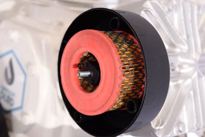
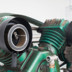
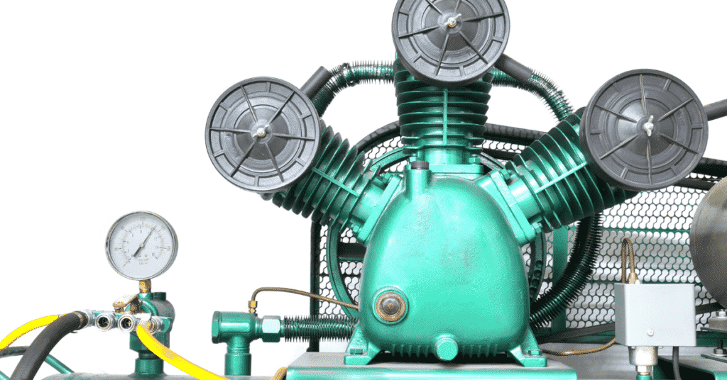
REPLACING AIR FILTER CARTRIDGE
The air filter must be checked at frequent intervals and approximately at every 250 hours or whenever the air discharge temperature becomes high.
The air filter element must be replaced with a new one and sufficient spares must be available onboard.
An air filter is the first step to keep the compressor healthy.
It must be noted that the air compressors are installed at a place where there is sufficient air supply to ensure the suction is never devoid of air.
ONE MUST MAKE SURE THAT THE OLD CARTRIDGE IS NOT BLOWN WITH AIR AND RE-USED, AS THIS MAY DAMAGE THE AIR FILTER.
Dirty air filters affect the volumetric efficiency of the compressor and so does the temperature of the inlet air to the compressor.
FREQUENCY: EVERY 2000 RUNNING HOURS.
CHANGING OIL
It is important that the oil must be changed according to the maintenance frequency as the lubricating oil is not only used for the lubrication of the running parts of the compressor but also to remove the heat generated during the operation of the compressor.
The compressor must be run for some time before the oil is changed as it ensures that all the sludge and particles are in suspension.
The oil should be completely drained by removing the drain plug and flushed with fresh oil before the oil is replenished back again.
The crankcase should be thoroughly cleaned as well with a lint-free cloth and must be checked for bearing wear as well.
TWO DIFFERENT GRADES OF OIL MUST NOT BE USED AND MIXED.
FREQUENCY: 1000 RUNNING HOURS.
CLEANING OIL STRAINERS
The oil strainer is generally a mesh in a plate which is supposed to be cleaned at defined maintenance intervals. The filter should also be cleaned when the oil is changed.
It should be cleaned by a solvent and blown with air.
FREQUENCY: 1000 RUNNING HOURS.
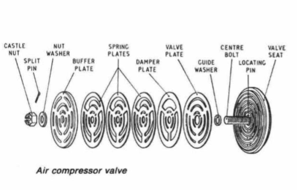
CHECKING VALVES
This is one of the most important jobs in the maintenance of the compressor. Hence extreme care must be taken while carrying out this job.
WHEN REMOVING AND INSTALLING A VALVE, EXTREME CARE MUST BE TAKEN THAT NO VALVE PARTS ARE DAMAGED. THIS APPLIES TO THE SEALING SURFACES OF THE VALVE.
Different types of compressors have different types of valves and removal methods for different stages
The valves must be removed and should be checked for leakage with diesel oil or water
The valves must never be held on vice but should rather be held on the tool given for the same.
All the parts must be properly cleaned after opening the valve and they must be checked for the carbonization as well. Over carbonization reveals that the oil topped up is more than required. This would lead to the sticking of the valves and eventually they would break.
Sticking of the valves will also reduce the volumetric efficiency of the compressor as the quantity of air discharged would be comparatively lesser.
The valve plate should be checked by pushing the valve plate from the side of the valve seat by a screwdriver. The valve plate will move a distance which is equivalent to a valve lift.
The springs and valve plates should be changed if required.
The plate could be lapped as well if no spares are available.
FREQUENCY: 3000 RUNNING HOURS FOR THE DISASSEMBLING AND CLEANING OF THE VALVE. 3000 HOURS FOR THE REPLACEMENT OF THE VALVE PLATE. 3000 HOURS FOR CHECKING THE FATIGUE OF THE SPRING AS WELL.
Related Reading: Troubleshooting Air Compressor On Ships
INSTALLING VALVES
All the valves must be re-fit with new gaskets and rings only. Only original spare parts must be used. Installing non-original gaskets may lead to compressor leaks and damage.
VALVES ARE THOSE PARTS OF A RECIPROCATING COMPRESSOR WHICH ARE MOST STRESSED, THUS THEIR MAINTENANCE MUST BE DONE CAREFULLY AND WITH EXTREME PRECISION.
HEAVILY CARBONISED VALVES DEPICT THAT THE LUBRICATING OIL HAS BEEN CARRIED OVER.
REPLACING VALVES
It is generally recommended by the manufacturer that the valves must not be repaired as they have a life and may fail due to fatigue. Thus, they must be replaced and the old ones disposed of.
The valves are supposed to be replaced in the same way as mentioned in the checking of the valves.
STICKING VALVES? WHY AND HOW DO THEY AFFECT THE COMPRESSOR?
If a valve is sticking, then it might add to the woes of the compressor as a sticky suction valve might lead to a loss in the air delivered because a part of air will be returned back to the suction side (with the valve not seating properly because of the carbon deposit or the spring being defective).
Similarly, if the delivery valve is sticking then a part of delivery air might return back to the cylinder during the suction stroke of the piston.
VALVE LIFT TOO HIGH? HOW DOES IT MATTER?
The valves with too high a lift will take a lot of time to re-seat and hence are liable to break at the piston delivery stroke as the pressure might be high for the valves to sustain.
INTERCOOLERS AND HOW TO CLEAN THEM?

Intercoolers are generally arranged after every stage of the main air compressor to reduce the work done in compressing the air by successfully cooling it down between stages. The intercooler is generally in the form of copper tubes bent in a U form. The air passes through the tubes and water circulates around them. These intercoolers could be a single tube type or straight tube type.
These types of intercoolers are provided with purge-spots to collect and drain water/oil which might find its way to the air coolers.
The intercoolers are generally opened up as per the maintenance frequency and are supposed to be cleaned by a solvent and the integrity of tubes to be checked as well.
They’re provided with a bursting disc in order to relieve the pressure in case a tube bursts.
The single tube type coolers are difficult to clean and the rate of wear is more than the straight tube types.
The straight tube types, on the other hand, could be plugged if they leak.
FREQUENCY: EVERY 3000 RUNNING HOURS.
CYLINDER LINER, COOLING JACKET AND PISTON
The air carries a lot of moisture in the cylinder liner which could wash away the lubricating oil film from the liner, thus causing liner wear which could also result in the scoring of the liner.
Thus, proper draining of the compressor is necessary to prevent the excessive liner and piston rings wear.
Cylinder liners could be lubricated by the oil splashed from the crankcase. They could also be lubricated by lubricating oil quills similar to the main engine delivered by an engine-driven lube oil pump.
The piston rings could wear in due time causing blow past and eventually reducing the volumetric efficiency of the compressor.
FREQUENCY: THE CYLINDER LINERS ALONG WITH THE COOLING JACKET ARE TO BE INSPECTED/CLEANED IN EVERY 3000 RUNNING HOURS OF THE COMPRESSOR. PISTON, PISTON RINGS AND OIL SCRAPER RING TO BE CHECKED IN EVERY 6000 RUNNING HOURS.
LUBRICATING OILS
Different manufacturers have different requirements for the use of lubricating oils. The compressors generally do not permit the use of synthetic lubricating oils with 3 stage air-cooled compressors because the good hydrolytic properties of synthetic oils cause moisture to condense in the crankcase thus there is a risk of corrosion and drive damage.
Because of their design, 3 stage air-cooled compressors have low final compression temperatures, rendering the high-temperature stability of synthetic oils useless.
THE JOBS ARE MORE OR LESS SIMILAR FOR ALL THE COMPRESSORS BUT AN INSTRUCTION MANUAL MUST BE STRICTLY FOLLOWED BEFORE CARRYING OUT ANY MAINTENANCE ON A COMPRESSOR.
Related Reading:
Disclaimer: The authors’ views expressed in this article do not necessarily reflect the views of Marine Insight. Data and charts, if used, in the article have been sourced from available information and have not been authenticated by any statutory authority. The author and Marine Insight do not claim it to be accurate nor accept any responsibility for the same. The views constitute only the opinions and do not constitute any guidelines or recommendation on any course of action to be followed by the reader.
The article or images cannot be reproduced, copied, shared or used in any form without the permission of the author and Marine Insight.
Do you have info to share with us ? Suggest a correction
Latest Marine Technology Articles You Would Like:

- Compressed Air Line On Ships – A General Overview

- Marine Air Compressor Maintenance – Things You Must Know About
- The Ultimate Guide to Air Compressors on Ships
- What is Clearance Volume or Bumping Clearance in Air Compressors?
- Troubleshooting Air Compressors on a Ship: The Ultimate Guide
- Safety Features and Maintenance Procedure for Air Compressor on a Ship

Subscribe To Our Newsletters
By subscribing, you agree to our Privacy Policy and may receive occasional deal communications; you can unsubscribe anytime.
Many thanks.
You are welcome. Thanks for stopping by!
I was given your website by some students appearing for an ‘Operations’ level of their Certificate of Competency. The material you have displayed is very nice for apprentices and trainees.
If you should decide to raise the bar for Certificates of Competency candidates, I would recommend that some research be carried out prior to composing your content. Typically, the following regulatory understanding would form a pre-requisite for any STCW III/1 CoC holder to carry his job covering air compressors, in a safe manner:
Starting Arrangements of Internal Combustion Engines from the IACS document (www.iacs.org.uk)
M61.1 Mechanical starting arrangements
M61.1.1 The arrangement for air starting is to be such that the necessary air for the first charge
can be produced on board without external aid.
M61.1.2 Where the main engine is arranged for starting by compressed air, two or more air
compressors are to be fitted. At least one of the compressors is to be driven independent of the
main propulsion unit and is to have the capacity not less than 50 % of the total required.
M61.1.3 The total capacity of air compressors is to be sufficient to supply within one hour the
quantity of air needed to satisfy M61.1.5 by charging the receivers from atmospheric pressure.
The capacity is to be approximately equally divided between the number of compressors fitted,
excluding an emergency compressor which may be installed to satisfy M61.1.1.
M61.1.4 Where the main engine is arranged for starting by compressed air, at least two
starting air receivers of about equal capacity are to be fitted which may be used independently.
M61.1.5 The total capacity of air receivers is to be sufficient to provide, without their being
replenished, not less than 12 consecutive starts alternating between Ahead and Astern of each
main engine of the reversible type, and not less than six starts of each main non-reversible type
engine connected to a controllable pitch propeller or other device enabling the start without
opposite torque. The number of starts refers to engine in cold and ready to start conditions.
Additional number of starts may be required when the engine is in the warm running condition.
When other consumers such as auxiliary engines starting systems, control systems, whistle,
etc., are to be connected to starting air receivers, their air consumption is also to be taken into
account.
Regardless of the above, for multi-engine installations the number of starts required
for each engine may be reduced upon the agreement with the Classification Society depending
upon the arrangement of the engines and the transmission of their output to the propellers.
Very good