

Compressed Air Line On Ships – A General Overview
Compressed air on ships is used for different purposes. High-pressure air of 30 bar is mainly used for the main engine starting.
This high-pressure air is reduced to lower working pressures through pressure reduction valves and is used for other important purposes.
The air at reduced pressures of 7-8 bar is used as service air for a number of applications.
Some of these include starting of Auxiliary Engines, Emergency Generators, Charging of freshwater and drinking water hydrophores, blowing the fog horn, spring air for exhaust valves of the Main Engine, dry washing of Main Engine turbochargers, for use in sewage treatment plants for aerobic sewage breakdowns, soot blowing of boilers, pneumatic pumps for oil transfers and many more applications such as service air for the use of cleaning, painting operations, chipping and operation of pneumatic tools such as grinders, chisels etc.
One more important branch of this 7-8 bar compressed air is used as control air. The control air is a filtered branch of the service air which is made free of any moisture and oil carry-over. This controlled air is used for pneumatic controllers and is important for the operation of machinery onboard ships.
This makes the air line on a ship a very important aspect of ship operations. This article throws light on the air line of a Ship in general, its important components and working.
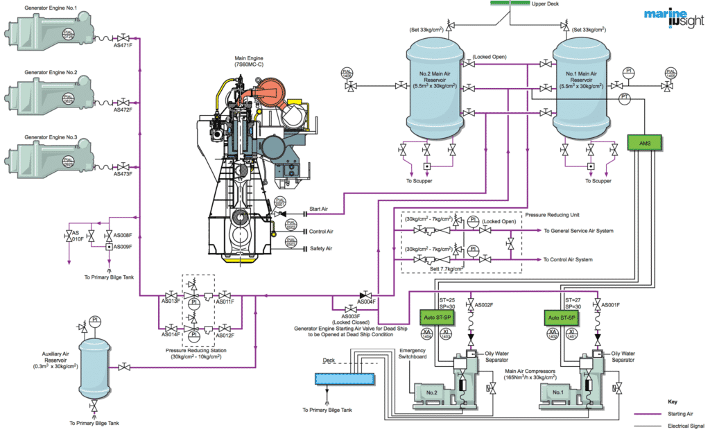
The complete pneumatic air line on a ship includes the Main High-pressure airline, the service air line and the control air line.
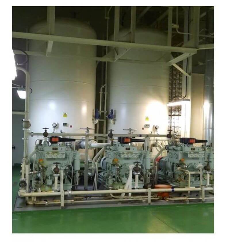
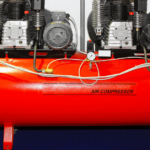
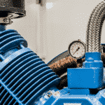
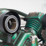
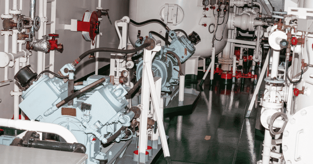
Main Air Compressor
The main air compressor is the heart of the air-line onboard. The air compressor compresses air by means of reducing its volume so as to raise its pressure. Air compressors can be of various types. They include
1. Centrifugal Compressors
2. Rotary vane compressor
3. Rotary screw compressors
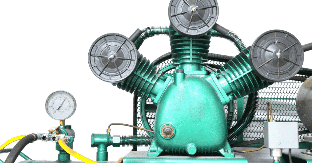
4. Reciprocating Air compressors
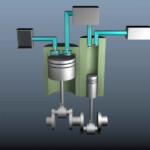
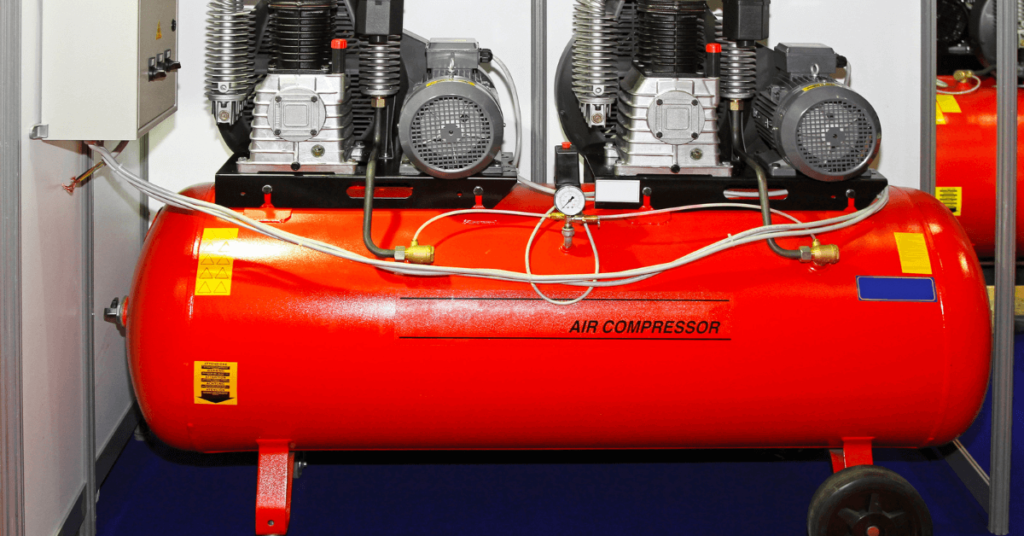
Most modern merchant vessels are employed with multi-stage reciprocating air compressors having intercoolers & aftercoolers with auto-draining and unloading arrangements.
The capacity of the main air compressor is expressed in terms of Free Air Delivery (FAD) and is stated in cubic mtrs /hour.
Free Air Delivery can be defined as the volume of air actually discharged by the compressor in 1 hour, that would occupy if expanded down to atmospheric pressure and cooled to atmospheric temperature.
The discharge of the main air compressor is led into a main air bottle or reservoir which stores this pressurised air at a maximum of 30-32 bar.
A ship may have 2 or 3 main air compressors depending upon many factors such as each air compressor capacity, amount of volume of air needed for starting of the Main Engine, demand of air on that particular ship etc.
The marine boilers and exhaust gas economizers on certain ships are soot blown with air, these ships may be employed with higher capacity air compressors at the design stage depending on ship owners.
As per SOLAS requirements, a ship’s main air compressors should be able to fill its air reservoirs from 0 to maximum pressure (30bar) within 1 hour.
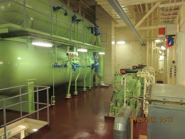
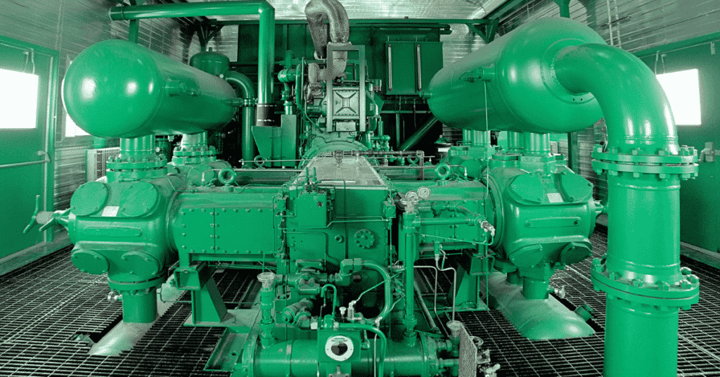
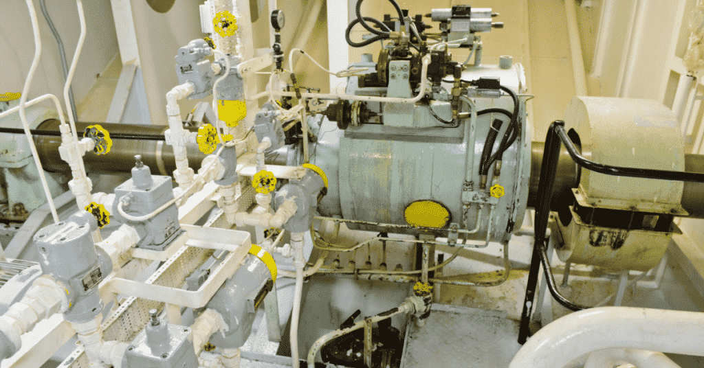
Main Air Reservoir
Each ship is equipped with a set of 2 air reservoirs. They may be of the vertical or horizontal type.
Air reservoirs are hydraulically pressure tested to 1.5 times its working pressure.
As Per Solas Regulations –
The total capacity of air reservoirs must be sufficient to give at least 12 consecutive Main Engine starts for a reversible engine, and at least 6 consecutive starts for a non-reversible engine without refilling of the reservoirs.
There must be 2 identical main air receivers and 1 emergency air bottle for every vessel.
Air Reservoir Mountings
Each air reservoir should be equipped with the following mountings:
1. Fusible Plug
Composition – Bismuth 50%, Tin 30%, Lead 20%
Melting Point: 220deg F (104.4deg cel) Fitted at the reservoir’s bottom or on the reservoir at the ship side when a relief valve (safety valve) is not directly fitted on the reservoir.
It is fitted to release the compressed air in the event of abnormally high compressed air temperature.
2. Atmospheric Relief Valve
It is provided as over-pressure protection and as a back-up of the fusible plug.
In case of an Engine Room fire when CO2 flooding is required, this valve is to be opened before evacuating the engine room.
(The air receiver relief valve opening could either open outside the engine room through the ship’s funnel or inside the engine room itself. In case of the latter, CO2 bottle calculations for fighting a fire in the Engine room is done accordingly and the extra CO2 required is taken into consideration at the ship’s design stage)
3. Spring Loaded Safety Valve
Setting pressure 32 bar (for a 30-bar working pressure) with equal to or greater than 10% rise in accumulation of pressure may be fitted directly or with extension.
4. Compensation Ring
When a hole is cut or machined into a pressure vessel, higher stresses will subject to the material around the hole, and to reduce this, compensation rings are fitted.
It is a flange on which a valve or fitting is usually mounted. A compensation ring provides for structural integrity in the air pressure vessel.
5. Manual Drain valve or Automatic Drain valve
6. Pressure gauges
7. Access doors
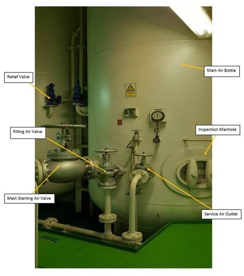
8. Main Starting valve, auxiliary starting air valve, fitting valve, service air or whistle air valve
Large cylindrical air bottles usually have one longitudinal welding seam. The longitudinal and circumferential seam is machine welded with full penetration welds.
The welding details are governed by the pressure of air that is to be stored in conjunction with classification society regulations.
All welded air receivers have to be stress relieved or annealed at a temperature of about 600 deg Celsius and the welding is to be radiographed for safety purposes.
Receivers are subjected to statutory survey and inspection, periodically hydraulic tested at 1.5 times the working pressure, is to be applied every 10 years for large receivers.

Air Bottle Inspection
Air receivers are to be inspected as per PMS and checked for any signs for corrosion. Moisture in air receivers can give rise to corrosion and despite the proper operation of compressor cooler drains, a large amount tends to collect, particularly in humid conditions.
It is good practice to check air reservoir drains regularly to assess the quantity of liquid present. In extreme conditions, drains may have to be used 2-3 times daily to remove accumulated emulsion. Mostly corrosion is found near the air receiver drain.
After thorough visual inspection, if required, thickness measurement can be done using an ultra-sonic thickness gauge. If the thickness of the air receiver is compromised, we have to reduce the air pressure to be contained in that particular air bottle.
This, after certain calculations, can be done by changing the cut-in, cut-off settings of the air compressor when that particular receiver is in use and relief valve settings have to be re-adjusted. Also, the air receiver can be isolated completely and kept on stand-by, can be filled manually with caution, whenever required.
All internal welds or small changes in cross-section need to be thoroughly inspected.
If the air bottle is too small to manually enter, then internal inspection can be carried out using a camera with a probe.
Internal Surface Coating
Should be graphite suspension in water, Linseed oil, Copal Vanish or Epoxy coating, having basic properties such as anti-corrosive, anti-toxic and anti-oxidation.
Safety Devices On Main Air Bottle
1. Fusible Plug
2. Pressure relief valve
3. Atmospheric Relief Valve
4. Low-Pressure Alarm
5. Automatic or Remote-control moisture drain valve
The Control Air System
A branched airline through a pressure reducing valve is supplied to the Control Air line.
Pneumatic control equipment is sensitive to contaminants which may be in compressed air. Viscous oil and water emulsions can cause moving parts in control equipment and control valves to stick and produce general deterioration of diaphragms, spools and other parts made of rubber.
Water can cause rust build-up which may also result in parts sticking or being damaged by these rust particles. Metallic wear and other small particles can cause damage by abrasion.
Any solids mixed with oil and water emulsions can conspire to block small orifices. Clean and dry control air is thus essential for the trouble-free operation of control- air systems.
When the source of control and instrument air is the main air compressors and the main air reservoir itself, then special provision is necessary to ensure that air quality is high.
The pressure reducing valve which brings the main air pressure to the 7 or 8 bar required by the control air system, can be affected by emulsion carry over and can require frequent cleaning to stop air contamination.
Automatic drain traps may be fitted in the control air system, but many have traps which require daily draining by the engine crew.
Large amounts of free moisture and oil emulsion carry-over in the air can be removed by special control-air membrane filters installed in the control air line.
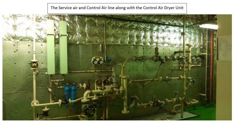
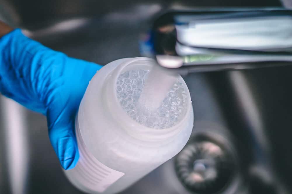
Control Air Filter
A typical control air filter arrangement consists of an oil & moisture collecting filter followed by a membrane air dryer filter. The treatment of air through these membrane filters results in the air being filtered and dried in order to remove virtually all traces of oil, moisture and air impurities.
A simple line air filter is provided with a small plastic float and auto drain arrangement.
The filter can also be drained manually if the vessel enters a highly humid environment and frequent draining is required.
The filter dryer unit is made up of a primary filter, secondary filter and membrane hollow fibre elements.
Air Flow Through The Control Air Dryer
The control air enters the dryer chamber through the line filter located in the lower part of the dryer unit. In the dryer unit, the primary filter removes the coarse rust particles, dust and other larger impurities.
The secondary filter acts like a coalescer, separating water droplets and oil mists up to 0.3 microns. A differential pressure gauge indicates the condition of the primary and secondary filters.
A higher differential pressure indicates a dirty membrane filter. The membrane elements are to be renewed as per the ship’s PMS.
Piping
The high-pressure air piping from the air compressor to the receiver should be as smooth as possible without any bends in the pipeline so as to allow air to flow freely to the receiver without restrictions. Bends in the piping can create backpressure in the line in case of accumulated moisture or oil emulsion in the line.
Emergency Air Compressor And Emergency Air Bottle
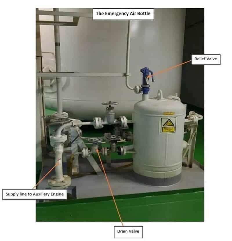
The emergency air compressor is a small independent air compressor which can be either driven by an independent prime mover like an engine or having a power supply from the emergency switchboard.
It is used to fill up the emergency air bottle which has a sufficient volume of air to start the auxiliary engine of a dead ship.
The control air onboard is also used in the Emergency Shut-Off Valve operating system.
An emergency QCV – Air bottle with 7 bar air pressure is used to operate all Quick Closing valves, fire and funnel dampers on board.
This arrangement consists of a 7 bar Emergency QCV air bottle with QCV- shut off valves that are to be always in a state of readiness.
In case of an uncontrollable fire in the engine room, the Quick closing valves are operated which supply this control air to SHUT specific outlet valves of all Fuel Oil and Lube Oil tanks and ER funnel and Blower dampers thereby cutting off all fuel and air supply.
Control Air Supply is also used on Emergency Shut Down Systems (ESDS) on Gas Tankers.
Disclaimer: The authors’ views expressed in this article do not necessarily reflect the views of Marine Insight. Data and charts, if used, in the article have been sourced from available information and have not been authenticated by any statutory authority. The author and Marine Insight do not claim it to be accurate nor accept any responsibility for the same. The views constitute only the opinions and do not constitute any guidelines or recommendation on any course of action to be followed by the reader.
The article or images cannot be reproduced, copied, shared or used in any form without the permission of the author and Marine Insight.
Do you have info to share with us ? Suggest a correction
Latest Marine Technology Articles You Would Like:
- Compressed Air Line On Ships – A General Overview

- Marine Air Compressor Maintenance – Things You Must Know About
- The Ultimate Guide to Air Compressors on Ships
- What is Clearance Volume or Bumping Clearance in Air Compressors?
- Troubleshooting Air Compressors on a Ship: The Ultimate Guide
- Safety Features and Maintenance Procedure for Air Compressor on a Ship


Subscribe To Our Newsletters
By subscribing, you agree to our Privacy Policy and may receive occasional deal communications; you can unsubscribe anytime.

Can you send me some books for application Pneumatics on vessels?
Greetings from Germany
Dipl.-Ing. Hermann de Vries
@Hermann:: Currently, we do not have ebook on pneumatics. https://learn.marineinsight.com
Hello sir,
Could you clarify where in SOLAS it is written that 12 consecutive starts are required? I have only found IACS notice M61 addressing this issue. SOLAS chapter II-1 part C rule 34 does not make any mention. There is a 3 start minimum capacity placed on emergency equipment, but not main or auxiliary engines.
Many thanks from Canada.