

What Is Moulded Depth Of A Ship?
We know basic parameters like length, breadth, depth, draft, etc., primarily denote a vessel. From a geometrical point of view, all these parameters essentially define the size of the vessel and, up to some extent, the vessel’s hull form.
For instance, a ship having a proportionally greater extent of length as compared to its breadth is said to have a slender hull form. In contrast, a vessel having a length not significantly greater than the breadth is said to have a bluff hull form.
However, the values of these parameters alone are not sufficient. For example, a vessel having a length of 100 metres and a breadth of 20 metres cannot be firmly labelled as a fine or bluff form ship. More information like the ratios of Length/Breadth or L/B, hull form coefficients and, of course, the physical form of the vessel is required.
We have previously discussed the parameters like length, breadth, draft, etc., in detail. Now let us talk a bit about the depth and moulded depth. What do we mean by the depth of a vessel?
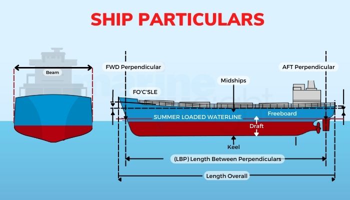
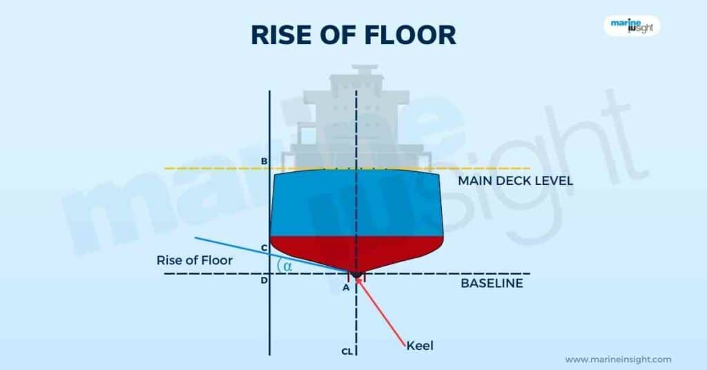
As the name very easily suggests, the vessel’s depth is the measure of the distance from the extreme bottom of the vessel to the main deck, bulkhead, or weather deck. In technical terms, the extreme bottom of the vessel is also known as the vessel’s keel and is usually coincident with the vessel’s centreline.
On the other hand, the main deck of the vessel is the most prominent deck and essentially the upper extremity of the hull. The main deck of the hull is also often known as the strength deck, as this is one of the major contributors to the hull girder’s longitudinal and transverse strength, along with the bottom shell and side shell platings.
Moreover, as this is the lowermost and often the biggest surface exposed to the effects of the external environment, the names exposed or weather deck are often used. Furthermore, as this is often the upper limit of the longitudinal and transverse bulkheads of the main hull, this is also known as the weather deck.

The superstructure or deckhouse, along with many items ranging from bollards to cargo stowage cranes, from guardrails to bulwarks, from rescue boats to ventilation ducts, are all situated on the main deck or exposed deck. The main deck is also a crucial access point between the hull and all other structures above it.
In most vessels, the main deck can be easily recognised simply by looking. However, in some cases, like big passenger vessels having a complete and continuous superstructure from aft to forward extremity, there is no exposure of the main deck surface which is identified as the upper end of the hull structure given. There are multiple main decks for special design vessels like multi-hull vessels, as obvious.
The depth is a significant parameter from the design point of view. However, an even more significant parameter than depth is the draft which is the distance of the waterline to the bottommost point of the hull and is always lesser than the depth for all practical purposes. The draft is a crucial parameter for all major ambits of marine design like stability, manoeuvring and seakeeping, resistance and propulsion and so on.
The mathematical difference between the depth and draft is known as the freeboard. The upper portion of the main hull, above the waterline that is not submerged, is also a measure of the reserve buoyancy from the stability point of view.
Now, what is moulded depth?
Before that, let us know what moulded parameters are. Note that above, the term ‘extreme’ has been used multiple times. So, all these parameters, like breadth, length, and depth, are measured in two ways. First is the extreme. Next is the moulded. So, moulded parameters are nothing but these measures, excluding the shell plating thickness. As we know, the outer skin of the hull is made up of steel plates. These plates have a definite thickness according to the design rules and regulations.
So, from a basic design point of view, the measures are taken without the value of the thickness. Hence, in a more technical definition, the moulded depth is the perpendicular or vertical distance measured along the vessel’s transverse plane from the top of the keel plate (which is the thickest part of the bottom shell plating), i.e., excluding the thickness of the bottom shell to the underside of the main deck, i.e., excluding the thickness of the main deck plating.
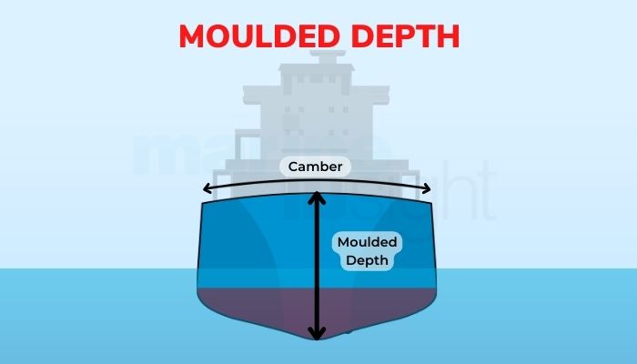
On the other hand, the extreme depth is measured along the same path but includes the thickness of the shell platings. Similarly, moulded values have a similar concept of shell thickness exclusion for other quantities and are measured according to the plane of consideration. The following figure explains better.
For all practical purposes in design, the moulded parameters are only considered. Why? Though the answer is slightly complicated, it can be simply said that for the placement of structural members and designing of internal spaces and tanks, the thickness is redundant and may often cause complications to the designer due to interference and even oversized structural members, which require to be again cut to precise size while the vessel is being constructed.
Also, other than the weight of the vessels from the point of view of displacement and mass, the thickness of the shell plating does not take any part in the disposition of the internal arrangement of the hull. For example, when a transverse bulkhead is placed, the distance between the top of the keel or bottom shell and the underside of the deck plating is required for its proper design, construction, and disposition.
For all practical purposes, while measuring the value of moulded depth to the top of the keel, it is taken at the side shell to avoid overestimating the effects of deck camber.
For vessels having gunwales at the sides, the moulded depth is measured from the topside of the bottom shell or keel to the point of intersection of the external angular projections of the rounded gunwale at the side. In simpler terms, along the side, the depth extends to the point of intersection of the tangents to the rounded corner, excluding the thickness of the given deck plating. The following figure explains better.
The intersecting red lines depict the deck’s and side shell’s projections about the rounded gunwale (in blue). The moulded depth ends at the top of the intersection.
You may also like to read-
- Understanding The Beam Of A Ship
- What is Sheer, Flare And Camber in Ships?
- What is Angle Of Loll in Ships?
- What Is A Ship Trim?
Disclaimer: The authors’ views expressed in this article do not necessarily reflect the views of Marine Insight. Data and charts, if used, in the article have been sourced from available information and have not been authenticated by any statutory authority. The author and Marine Insight do not claim it to be accurate nor accept any responsibility for the same. The views constitute only the opinions and do not constitute any guidelines or recommendations on any course of action to be followed by the reader.
The article or images cannot be reproduced, copied, shared, or used in any form without the permission of the author and Marine Insight.
Do you have info to share with us ? Suggest a correction


Latest Naval Arch Articles You Would Like:


Subscribe To Our Newsletters
By subscribing, you agree to our Privacy Policy and may receive occasional deal communications; you can unsubscribe anytime.
Web Stories


About Author
Subhodeep is a Naval Architecture and Ocean Engineering graduate. Interested in the intricacies of marine structures and goal-based design aspects, he is dedicated to sharing and propagation of common technical knowledge within this sector, which, at this very moment, requires a turnabout to flourish back to its old glory.