

Hull Fairing And Development: Why And How
Remember how you might have created many things out of paper folding such as animals, flowers etc. back then you had actually learnt the concept of development of 3D dimensional objects starting with 2D laminas (e.g. paper). Now, let us think of something quite complex in three-dimensional terms but quite large in size. Yes, I’m talking about a ship’s hull.
How would you design a ship hull with all its curvatures and characteristic intricacies such that it doesn’t become too complex for production? Obviously, you would search for ways to break it down to smaller manageable pieces which can be easily processed in the workshop as the workshop has to find out practical ways to create a scaffolding/loft for bringing the desired hull shape to reality.
The concept of development of the hull plating for production is a very relevant one even in today’s CAD (Computer Aided Design) era. The ship hull is designed on a software platform which enables the user to visualise the 3D problem (Representation of the three-dimensional hull lines as 2D equivalents in various sections i.e. the sheer plan, half breadth plan and the body plans) in an intuitive manner. By making changes in any one of these sections, the user effectively manipulates the lines in 3D changing the other sections instantaneously.
Given this great advantage, we come to the actual problem of fairing a hullform while keeping the curvature developable with plating. Fairing often tends to get many definitions across literature, but it effectively serves certain purposes:
• Superior hydrodynamics: optimal vessel speed, low resistance, increased fuel efficiency, manoeuvrability, etc.
• Aesthetics: appeal to the human senses, functionality after life cycle (e.g. conversion to resorts, display in museums, etc.)
However well built a vessel might be, it might serve its purpose very well, but the finishing and fairing job done reflects the shipbuilder’s attention to the tiniest of details and is often a matter of pride for them. Finishing and fairing are often considered among the finer arts of shipbuilding.
For a moment, think of you have the job of producing a smooth surface out of a body with a coarse surface, you have the option of removing away the high points on the surface until you reach a low level (something often done with wood), also you have the option of adding material to reach a higher level to maintain evenness (paints and surface applications) you could also take some material from the higher planes and deposit it on the lower planes to reach a degree of smoothness.
Shipbuilding employs paint, surface preparation, and many other techniques to achieve the level of finishing of modern-day standards.
A ship hull is composed of numerous steel plates which are rolled or bent to give the characteristic shape at some section. Take a look here at a ship’s shell expansion plan:
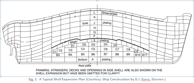
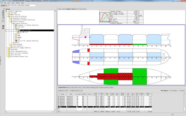
This represents the developed surface of the plating used (at plate level) in the manufacture of a vessel and often gives an estimate of the steel to be used in manufacturing the ship. But since the development of a shell expansion plan comes quite later in to the ship’s design cycle, the designer is faced with the problem of ensuring that the hull surface is fairly developable. This is where software comes in. Advanced ship design productivity suites like MAXSURF or DELFTship provide fairing modules for this. The principle on which these are based is that the curvature of a certain ‘patch’ or element in the hull skin can either stand for single/multiple or positive/negative curvatures for the collection of points within it.
Certain typical representations of such curvature are as follows:
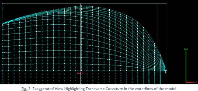
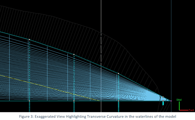
1.) In ship designs, the transverse curvature is particularly higher than the longitudinal curvature and so it might be helpful to exaggerate the transverse curvature in view to aid the designer in finding out the inconsistencies (if any) in the fairness of the model. For this reason, some programs allow this to be represented as one of the rendered forms.
2.) Another important tool allows us to modify particular waterline contours based a graphical representation of the curvature along the contour, often called curvature porcupines. Notice the radially outward emerging lines in grey? The height of these lines are proportional to the amount of curvature inherent at the location. Even a slight change in control point position alters these greatly and hence offer a better intuitive experience of fairing. In the event an outward emerging porcupine ends up inside the waterline, the section indicates a hollow in the hull surface and needs rectification. The porcupine curve which runs along the porcupines should be fairly smooth, if not, then there are options to change the stiffness of the control points used in the model.
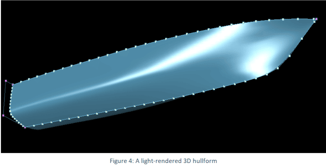
3.) One popular and simple way of evaluating the fairness is by using the rendered hull using lighting highlights. This shows how light would bounce off the surface of the hull around the hull and often is useful in creating promotional and non-technical content too. This tool entirely depends upon the user’s perception and can only be used for major bumps/irregularities.
Read the full article on the Navisieger magazine here
This article is authored by Sudripto Khasnabis and was originally published at the inaugural issue of Navisieger. Navisieger is a magazine published by Learn Ship Design. It is a confluence of insights on the maritime technology sector taken from academic experts, naval architects, industry veterans in this field, in the form of articles and exclusive interviews. Learn Ship Design is the first student initiative in India that works towards enhancing industry-academia engagements in the maritime sector.
Do you have info to share with us ? Suggest a correction


Latest Naval Arch Articles You Would Like:
Subscribe To Our Newsletters
By subscribing, you agree to our Privacy Policy and may receive occasional deal communications; you can unsubscribe anytime.