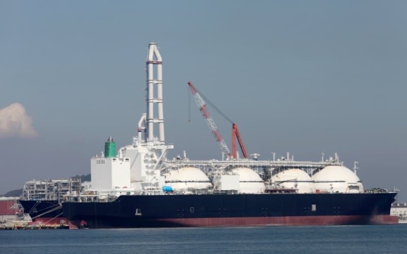
Properties Of Membrane Tanks For Transportation Of LNG Cargo On Ships
LNG as fuel is now a proven and available solution for the shipping industry. While conventional oil-based fuels remain the main fuel option for most existing vessels in the near future, the commercial opportunities of LNG are interesting for many new build and conversion projects.
LNG (liquefied natural gas) is a natural gas (example methane) in liquid form and is supposed to be known as the cleanest combustible fuel. It is comparatively available in abundance and relatively inexpensive. According to a latest report, United States leads in LNG usage, with 76% of U.S homes using LNG as a heating fuel.
Properties of LNG
As discussed earlier, LNG is a liquid form of natural gas, condensed at -160 degrees C at atmospheric pressure.
Unlike Natural Gas (CNG), LNG is compressed into liquid for transportation as gas occupies more space. Transportation of CNG (Compressed Natural Gas) exploits the Boyle’s Law (At constant temperature and mass, the pressure is inversely proportional to volume) to occupy less space compared to Natural gas, but still it falls behind LNG.
For example, take 1000 kg of LNG and CNG each. Let’s construct a tank to accommodate either of these fuels and compare the minimum tank capacity required to accommodate them.
Density of LNG is 450 kg/m3 (approx.) @ -160 degree C (Atm. Pressure)
Density of CNG is 194 kg/m3 (approx) @ 30 degree C (250 bar)
Also, CNG tanks are subjected to high pressure (over 200 bar) hence the tanks (also associated pipelines) have to comply with high-pressure vessel design regulation and all safety regulations of high pressure vessel. This gives LNG carriers an advantage over CNG carriers considering the economic and safety factor.
Types Of LNG Cargo Tanks
LNG tanks are manufactured keeping in mind the various properties of the liquified natural gas as discussed in the above paragraph. There are three major types of LNG containment system used in ships:
1.Membrane type
2.MOSS type
3.Prismatic type
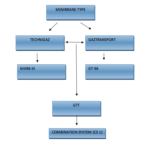
Membrane type containment system is further classified as below:
(The two major designers of membrane type cargo tanks are Gaztransport and Technigaz.)
1. Mark-III
Mark-III was originally designed by Technigaz. It consisted of – Primary membrane: Stainless Steel (304L) Thickness 1.2 mm-Corrugated, Secondary membrane: Triplex, Insulation:160 mm thick Polyurethane foam reinforced with fibre glass. (The thickness of the insulation is based on the allowable Boil Off Rate (B.O.R).)
2.GT-96
GT-96 was originally designed by Gaztransport. In this, both primary and secondary membranes are Invar (0.7 mm thickness). Primary and secondary insulations are plywood boxes filled with perlite.
3.CS-1
GTT designed CS-1 which is combination of Mark-III and GT-96 .
Here the primary membrane is Invar and Secondary membrane is triplex.
Material Selection
It’s interesting to know that the material used for this membrane is stainless steel and not carbon steel. Moreover, the thickness of the membrane is very less (Mark III –stainless steel of 1.2 mm, GT-96 –Invar of 0.7 mm). This is because materials behave differently at different temperatures. The characteristics of the material changes when the temperature is vastly changed. Most importantly impact energy of the material is significantly diminished at cryogenic temperature. The point to note here is the Ductile to the brittle transition temperature (DBTT).
Ductile to brittle transition temperature
Materials when experience a very low-temperature exhibit ductile to brittle transition, also known as Nil ductility transition (NDT), i.e. material loses its ductility at this stage.
Ductile materials deform before they fail. Simply put they give a warning sign before they fail, while brittle material fail without giving a warning sign, exhibiting catastrophic failure (e.g. glass).
For an LNG cargo containment system, it is important to note that the material of the membrane that is in contact with the cargo should have very low ductile to brittle transition temperature (DBTT).
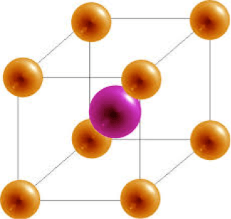
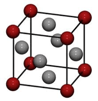
Crystal Structure
The characteristics of the material used for construction are determined by the crystal structure, which depicts the arrangements of the atom. Material with Face-centred cubic structure (e.g. Austenite stainless steel, Invar) does not exhibit ductile to brittle transition while the material with Body-centred cubic structure (carbon steel ) has a very high DBTT.
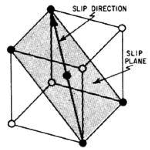
Why FCC metals are highly ductile?
FCC metals are highly ductile because of the concept called slip system. Slip planes are the direction in which the crystallographic plane dislocate. It is easier for the material with high atomic density to slide against each other and cause a plastic deformation; whereas on the other hand, BCC requires very large shear stress to get deformed as they are loosely packed and therefore these materials fail before they deform.
This is analogous to bicycles falling in a parking lot. For example in a parking lot, if bicycles are closely packed (parked), only a small amount of force is required for numerous bicycles to fall, similarly since the atoms are closely packed in FCC metal they tend to deform and then fail.
Heat Transfer
Another important factor which is taken under consideration while selecting the material for manufacturing LNG cargo tank is the heat transfer characteristics of the material. Heat transfer is normally related to the property and thickness of the material. Thicker the insulation lesser the heat transfer.
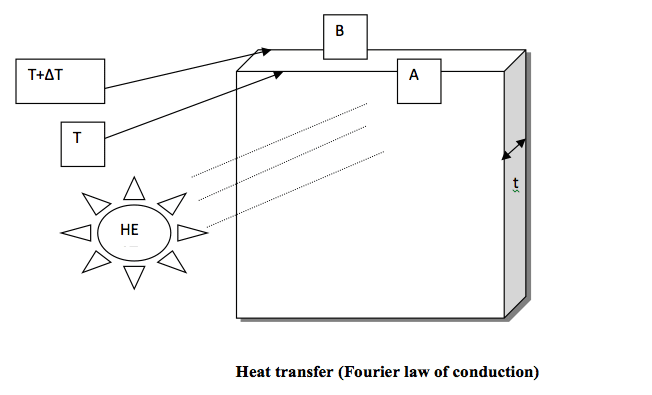
For assessing the Heat transfer from A to B , we use the Fourier law of conduction.
Q=k A ΔT/t
Where Q is heat transfer rate, K is thermal conductivity coefficient, ΔT is changing in temperature, t is thickness.
From the above equation, it is evident that rate of heat transfer rate is reduced with increase in thickness.
Insulation prevents the tank from the external heat, and hence reduces boil off (Vaporisation of LNG).
Sometimes insulation is designed in such a way so as to allow a certain amount of boil off, which is later used as a fuel.
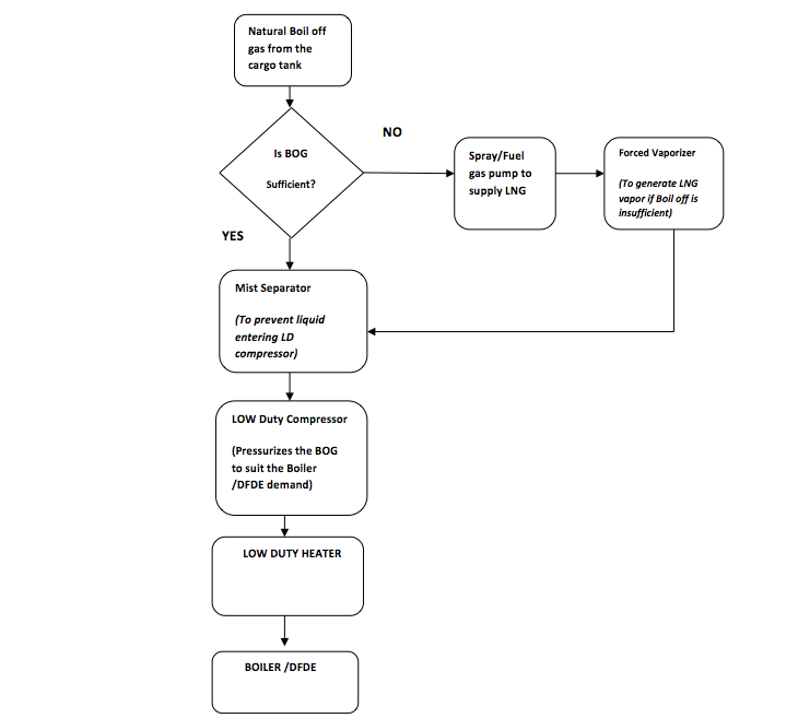
Boil Off Gas
This particular characteristic of LNG is also considered in selecting the material for tank construction as said earlier. The thickness of the insulation is based on the allowable Boil Off Rate (B.O.R).
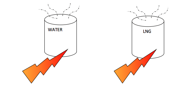
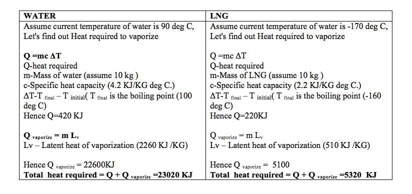
LNG being very volatile, vaporises very easily. Following comparison of water and LNG explains how easy it is to vaporise LNG.
Two major possible ways in which Boil Off Gas is generated:
1)Heat ingress
2)Sloshing effect
BOG management is very important as they affect the cost due to loss of cargo and the safety of the system (they increase the tank pressure ).
Boil Off Gas AS Fuel (Flow Chart)
LNG Tank Construction
Most common welding techniques used in LNG tank construction is TIG welding and plasma welding.
Plasma welding has a slight advantage over TIG welding due to its higher welding speed. This enhances the productivity.
The quality of the weld is ensured by visual examination and dye check ( ASTM 165 standard).
Welding of membrane sheet:
Membrane sheets –Steel corners: 1.2 mm membrane sheets are welded to the 8 mm steel corners. Before full continuous welding, preliminary tack welding is done to position the membrane sheet.
A similar principle is carried out on overlap welding of membrane sheet to membrane sheet.
According to class (ABS ), pitch of the tack welding should be 50-70 mm.
Intermittent welding makes connection of membrane sheet to the anchor strips .
It is important to note there should be no welding on the fixation rivets.
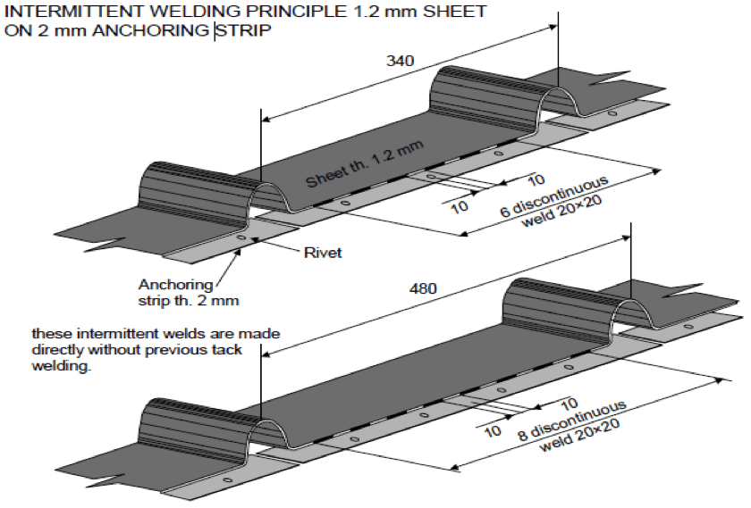
These fixation rivets are made of aluminium and dilution of aluminium can lead to fracture.
Welding defects and repair methods as described by ABS
1)Weld overlap/excessive convexity: Remove the excessive weld metal
2)Excessive concavity /craters /undercut: Prepare the surface and remelting the weld with or without filler metal
3)Incomplete fusion : Grind the unacceptable portion and re-weld
Acceptable criteria:
1)Width of the weld seam: 3mm<= 4.8mm
2)Gap before welding: 0.3 mm
3)Oxidation in back side: Flat part:10 mm, corrugation:20mm ,
4)Weld throat :>0.8mm
Panel Bonding to the inner hull: Epoxy Mastic( a mixture of resin and hardener ) secures the panel to the inner hull. Elastic behaviour of the epoxy mastic compensates the local hull deflection.
Triplex Bonding: Tightness of the secondary barrier is dependent on triplex bonding. Epoxy glue ensures the bonding to the panel (520 gr/m2).
Tank Tightness Test:
Helium Leak Test
In this test, helium is introduced into insulation layer and over pressurised. A vacuum chamber (hood) is placed on the welding seam to be tested. The role of the hood is to suck the leaking helium.The detector gathers all the helium ion, where the signal strength is then translated to the leak rate.
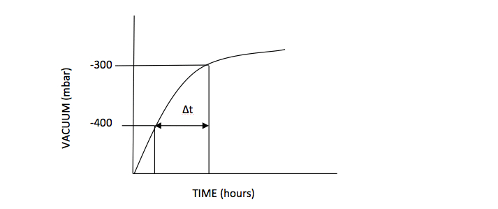
Secondary Barrier Tightness Test – Vacuum Decay Test
N2 or Dry air is used in vacuum decay test. A preliminary test is conducted before commencing the actual test to ensure the system is working properly.
A pressure difference is created between the primary and secondary space. The primary space is maintained at atmospheric pressure whereas secondary space is subjected to about -500 mbar. The pressure rise is monitored over a period (usually 12 hours) and vacuum decay curve is plotted.
How the integrity is evaluated?
Integrity is evaluated based on normalised Porosity Area (NPA). Regulation says
NPA<=0.85cm2 .
NPA =(1.210 X 10⁻³ VIS )/(ASB X Δt)
ASB – Secondary barrier surface area
VIS -Volume of secondary barrier
Δt-Time taken from -400mbar to -300 mbar
The type of containment system used for transportation of Cargo depends on several factors such as the type of cargo, possible effects on the structure, ways to tackle the them etc.
Over to you..
Do you know more points of membrane type containment system that can be added to the article? Let’s know in the comments below.
First we learned about the LNG itself, mainly its properties, possible effects of having a cryogenic liquid inside a tank, heat transfer, selection of material, some basic rules of welding and how the integrity of welding is ensured via helium test and SBTT. Remember the article is restricted to Membrane type of LNG cargo tank ,other significant type is MOSS Rosenberg.
Do you have info to share with us ? Suggest a correction
Latest Marine Technology Articles You Would Like:

- 10 Harmful Effects Of Impure Air On Ship’s Machinery

- 10 Important Things to Check While Starting Fuel Oil Purifier on Ships
- 10 Noteworthy LNG-Powered Vessels
- 10 Points for Efficient Turbocharger Operation On Ships
- 10 Practical Tips to Handle Engine Room Pumps
- 10 Precautions to Take Before Operating Controllable Pitch Propeller (CPP) on Ships


Subscribe To Our Newsletters
By subscribing, you agree to our Privacy Policy and may receive occasional deal communications; you can unsubscribe anytime.
Web Stories