

How to Synchronize Generators on a Ship?
Synchronization of Generators is the process of matching parameters such as voltage, frequency, phase angle, phase sequence, and waveform of an alternator (generator) or other sources with a healthy or working power system. A generator cannot supply electricity to an electric power system unless its voltage, frequency, and other parameters are precisely matched to the network. The exciter current and the generator’s engine speed are controlled to achieve synchronization.
Synchronization is primarily needed when two or more alternators work together to supply power to the load. Electrical loads are very inconsistent and they vary with time (depending on the load) and so it is necessary to interconnect the alternators operating in parallel to supply larger loads.
It ensures that the various parameters of one alternator ( or generator) resonate with another alternator or with the bus bar. The process of synchronization is also known as Paralleling of Alternators or Generators.
The synchronizing of the generator is done with the help of a synchroscope or with the three-bulb method in case of an emergency. It is of utmost importance that before paralleling the generators, the frequency and voltage of the generators need to be matched. In this article, we will describe the method for synchronizing generators on a ship.
Structure of Synchronous Generator
The synchronous generator comprises a rotor and a stator similar to a standard generator. The rotor consists of an electromagnet that rotates in the stator. The stator comprises windings that induce a 3- phase voltage and it consists of three stationary coils known as a stator, armature, or phase coils. Magnetization is also crucial for the stator windings because in absence of magnetic fields there are no forces to create currents.
To calculate the synchronous speed of the generator we use the formula-
Ns=(120 * f) / P
Where:
Ns = Synchronous speed, rpm
f = Frequency, Hz
P = Number of poles
120 is a constant for the time (seconds/minutes) and pole pairs, to get the speed in rpm.
Requirements for Synchronization or Paralleling of Generators
There are certain conditions that have to be met for the successful paralleling of generators. The underlying conditions must be met in order to synchronize a generator to the grid or with other generators.
Phase Sequence
The phase sequence of the three stages of the alternator connected to the power system bus must be identical to the phase sequence of the three phases of the bus bar (or electric grid). This issue usually arises during the initial installation or during routine maintenance.
Voltage Magnitude
The incoming alternator’s RMS voltage should be the same as the bus bar or electric grid’s RMS voltage. There will be a lot of reactive power flowing from the generator into the grid if the incoming alternator voltage is higher than the bus bar voltage.
The generator absorbs the high reactive power from the bus bar if the input alternator voltage is lower than the bus bar voltage.
Frequency
The frequency of the incoming generator must match the bus bar’s frequency. Inadequate frequency matching causes the prime mover to accelerate and decelerate rapidly, increasing the transient torque.
Phase Angle
There should be no phase angle between the incoming generator voltage and the voltage of the bus bar. By comparing the occurrence of zero-crossing or peaks in the voltage waveforms, this can be seen.
Methods to Synchronize Generators on a Ship
There are two methods to synchronize generators on a ship – one is the normal and the other is the emergency method.
1. Synchroscope method
A synchroscope is used to check the consequent frequency difference between the generators and the grids’ voltages.
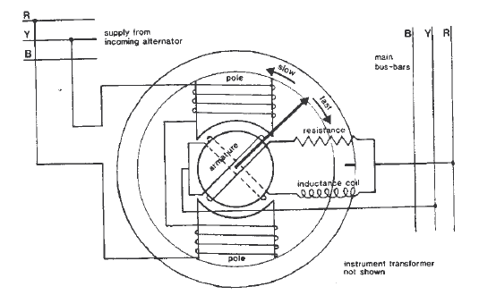
- The synchroscope consists of a small motor with coils on the two poles connected across two phases. Let’s say it is connected in red and yellow phases of the incoming machine and armature windings supplied from red and yellow phases from the switchboard bus bars.
- The bus bar circuit consists of inductance and resistance connected in parallel.
- The inductor circuit has the delaying current effect by 90 degrees relative to the current in resistance.
- These dual currents are fed into the synchroscope with the help of slip rings to the armature windings which produces a rotating magnetic field.
- The polarity of the poles will change alternatively in the north/south direction with changes in the red and yellow phases of the incoming machine.
- The rotating field will react with the poles by turning the rotor either in a clockwise or anticlockwise direction.
- If the rotor is moving in a clockwise direction this means that the incoming machine is running faster than the bus bar and slower when running in an anticlockwise direction.
- Generally, it is preferred to adjust the alternator speed slightly higher, which will move the pointer on the synchroscope in a clockwise direction.
- The breaker is closed just before the pointer reaches the 12’o’clock position, at which the incoming machine is in phase with the bus bar. This is because it takes a few more milliseconds for the contactor to pull in, so one starts the operation a little early.
- When the synchroscope is approaching 12 o’clock the “slip” between the sine waves is approaching minimum at 12 o’clock and the voltage differential between the phases is also minimal at 12 o’clock. By closing the breaker at 11 o’clock, we are achieving closing close to 12 o’clock.
Pros and cons of the Synchroscope method
- It is more accurate than lamps.
- The element of a personal judgment of the operator regarding the exact instant of synchronizing is nearly eliminated.
- It is costlier than lamps.
- It does not indicate the phase sequence.
2. Emergency synchronizing lamps or three bulb method
This method is generally used when there is a failure of the synchroscope. In case of failure, a standby method should be available to synchronize the alternator, and thus the emergency lamp method is used.
Three lamps should be connected between three phases of the bus bar and the incoming generator should be connected.
- The lamps are connected only in this manner because if they are connected across, the same phase lamps will go on and off together when the incoming machine is out of phase with the switchboard.
- In this method, the two lamps will be bright and one lamp will be dark when the incoming machine is coming in phase with the bus bar.
- The movement of these bright and dark lamps indicates whether the incoming machine is running faster or slower.
- For e.g. there is a moment when lamp A will be dark and lamps B & C will be bright, similarly, there will be instances when B is dark and others are bright and C is dark and the other two are bright. This example indicates that the machine is running fast and the movement of the lamps from dark and bright gives a clockwise movement
- Clockwise movement indicates fast and anti-clockwise direction indicates slow running of the incoming generator.
The ON and OFF rate of these lamps is determined by the frequency difference between alternator-2 voltage and bus bar voltage. As a result, the flickering rate must be lowered to match the frequency. This is accomplished by regulating the alternator’s speed via the prime mover control.
The bulbs will turn dark once all of these parameters have been established, and the synchronizing switch can then be closed to synchronize alternator-2 with alternator-1.
The biggest disadvantage of this method is that it only shows the difference between the alternator-2 and the bus bar by measuring the rate of flickering. However, this method does not provide information on alternator frequency in relation to bus bar frequency.
3. Two Bright and One Dark Lamp Method
This method can be used to determine whether the alternator frequency is lower or higher than the bus bar frequency.
- Similar to the dark lamp approach, the light L2 is linked across the pole on the middle line of the synchronizing switch, however, the lamps L1 and L3 are connected in a transposed manner.
- The voltage condition testing is similar to the previous approach, and the lamps will glow bright and black one after another after that. The order in which the lamps become dark and bright determines whether the alternator frequency is lower or greater than the bus bar frequency.
- The entering generator frequency is higher than the bus bar frequency, as indicated by the sequence of becoming bright and dark L1- L2 – L3. As a result, prime mover control must be used to reduce the alternator speed until the flickering rate is reduced to a minimum.
- The flickering L1-L3-L2 sequence, on the other hand, indicates that the incoming alternator frequency is lower than the bus bar frequency.
- As a result, the prime mover increases the alternator’s speed until the rate of flickering is reduced to as low as possible. When lamps L1 and L3 are both equally bright and lamp L2 is dark, the synchronization switch is closed.
The downside of this method is that the phase sequence’s validity cannot be verified. This criterion, on the other hand, is superfluous for permanently connected alternators, where confirming the phase sequence is sufficient for the first time of operation.
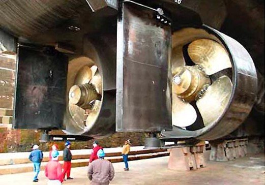
References and Image Credits: marine electrical equipment and practice by H.D Mcgeorge, generator arrangement – www.boatnerd.com
Do you have info to share with us ? Suggest a correction
Latest Marine Technology Articles You Would Like:


- 10 Situations When Ship’s Generator Must be Stopped Immediately

- 10 Important Tests for Major Overhauling of Ship’s Generator
- 8 Important Points To Note For Maintenance Of Emergency Generators On Ship
- Understanding Different Operational Modes Of Shaft Generator On Ships
- Ways of starting and testing emergency generator
- What’s The Criteria For Reuse or Replacement of Auxiliary Engine Connecting Rod On Ships?


Subscribe To Our Newsletters
By subscribing, you agree to our Privacy Policy and may receive occasional deal communications; you can unsubscribe anytime.
Helpful blog, bookmarked the website with hopes to read more!
Hi
We update our website regularly. Just surf around and you will find loads of useful information. Also, please do let us know if there is anything specific you will like to read on and we will get it published for you.
Thanks
Raunek
Editor
Your website is giving me more information in details compare to others..thanx
Glad to know the website has been informative for you.
@runekk, good stuff! nice description of synchronizing a ship’s generator..not mentioning the “auto-synchronizing”,(as i experienced) nowadays operators explicitly dependent on this auto-mode, However; when auto-mode fail they forget the BASIC, as when the vessel is underway at critically heavy traffic, channelling, etc where electrical power is very important – that may lead to catastrophic events. no offend.
very nice website.i’ll be grateful to this site.this is very beneficial for marine students..a lot of thanks………..
Excellent website. Please supply more pictures and movies. So we can easily do it onboard.
Excellent web page.
Actually we close the breaker before 12 o’clock (10 or 11 o’clock) for human delay. And incoming generator should also have a frequency a bit higher than running generator so that incoming generator can take load.
For detail synchronizing procedures, please refer to videotel series generator movie.
Glad you liked it Sir!! Thanks for your inputs!!!
Im going up for my MCA orals exam in a couple of weeks and this site has been a big help….thanks
Glad to hear it has been helpful!! All the best for exams!!
very good site for mmd oral preparation
relay helpful this one for our knowledge.plz can somebody explain me what will happens if we give the load for incoming generator when the synchronizer on six “o” clock position.
Gland to thank for such a important information
I would like some info on how & why three air conditioning compressors should be stage on start up & shut down
thnks but i have a question….Why is it unsafe to close the breaker of an incoming generator if the voltage is not the same as in the main board??? and what would happen if you do????
Thanks…
Can anyone explain how to test a Paralleling Impulse Transmitter (PIG 21)
Thanks
Great site, thanks a lot
very helpful for our MCA oral exam.thanks
Hi fellows
I’ve a question regarding governors. On board, the governors work in speed droop mode or isochronous mode?
Isochronous mode would be my answer, controlled by a load sharing device
Let me know if I’m wrong
Thanks
reunekk, thanks for your useful website, make me read more about engineering electricals. kindly educate me on this isssues. differente bt insulated neutral and earthed neutral distribution system.
2- which is used most on ship and why?
thanks
very helpful.
in synchroscope method of paralleling of generators..
why the inductor circuit has delaying current effect of 90 degree relative to current in resistance
Why do we close the switch at 11 o’clock and not at 12 o’ clock?
It takes a few more milliseconds for the contactor to pull in, so one starts the operation a little early. When the synchroscope is approaching 12 o’clock the “slip” between the sine waves is approaching minimum at 12 o’clock and the voltage differential between the phases is also minimal at 12 o’clock. By closing the breaker at 11 o’clock, we are achieving closing close to 12 o’clock.
How to parellel the generators when there is a defect in synchronizing panel…
@Nabeel,
Please find the answer to this question in our forums:
https://forums.marineinsight.com/forum/marine-engineering/3681-paralleling-generator-with-defective-synchrometer
Dear sir.. I can’t find any diagram for lamps connection related to Emergency synchronizing lamps or three bulb method
@Ankit: Will try to update and add the diagrams in the article in coming days.
Why we off synchronoscope after paralleling generators.
@Saurabh: Synchronizing circuits are usually designed not to be energized continually, due overheating of the coils in the scope and associated resistance units, if applied.
There is also no reason to have the syn circuits remain energized after the CB has closed. In well-designed systems, there has to be a selector system that selects the circuits to be synced and disconnects these circuits afterward, manually or automatically.
GOOD DAY SIR,
THE DIAGRAM FOR LAMP METHOD Synchronizing IS NOT AVAILABLE , IT WILL BE HELPFUL IF THE DIAGRAM IS POSTED FOR THIS METHOD ALSO THANKING YOU.
@Allwin: Noted. We wil pass this to our editorial team.
Anyone can share auto sync. Methodology.