

Globe Valve Used on Ships : Design and Maintenance
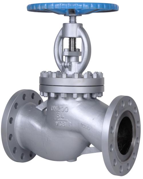
Glove valve, a type of valve, is commonly used on board ships in places such as bilge suction lines. A linear motion valve, which regulates the flow of the fluid, the valve has a globe (bulbous) shaped body that houses the valve seat and the disc.
The general arrangement of a globe valve consists of the valve seat and the disc arranged at right angle to the axis of the valve. The perpendicular movement of the disc, away from the valve seat, causes a space between the disc and the disc ring, which opens the valve.
This characteristic provides good throttling ability to the globe valve which is extremely helpful in regulating the flow of the fluid. The globe valve is used not only in starting and stopping the fluid flow but also for regulating the same.
Construction of Globe Valve
Though the construction and design of globe valve is usually made according to the requirements, there are three main designs of the globe valve
- Z-body type valve
- Y-body type valve
- Angle valve
Z-body type valve
This is the simplest and most commonly used design of globe valves, favorable for applications involving water flow. The name Z-shaped is derived from the Z shaped diaphragm or partition in the bulbous shaped body. The stem and the disc move at right angle to the valve body, aligning with the horizontally arranged seat. The stem passes through the bonnet attached to a wide opening at the top.
Y-body type valve
The Y-body type valve design is a solution to the problem of pressure drop which is commonly found in globe valves. In this design, the valve seat and stem are angled at approximately 45° to the valve axis. This results in a much straighter path for the fluid flow, providing a more pressure resistant environment inside the valve.
The Y-body valves are mainly suited for high pressure applications wherein problems related to pressure drop are common. However, in case of throttling purpose, the pressure resistance might not work effectively, especially if the valve is smaller in size. This is also because in smaller valves, the flow passage is not as carefully streamlined as that in larger vessels.
Angle Valve design
The angle globe valve is a modification of the design of the basic Z-shaped glove valve. The inlet and outlet ends are placed at right angles and the diaphragm is generally a simple flat plate. The fluid flows through the valve body in a right angled flow path and get discharged downwards in a more symmetrical manner. These characteristics are extremely important in applications involving high pressure. However, in moderate conditions the valve functions more or less similar to the Z Shaped Valve.
Globe valves are used for both low and high temperature applications. In low temperature applications the globe valves are so installed that the pressure is under the disk. This helps in easy operation of the valve and also for protecting the packing and preventing erosion to the seat and disk. For high temperature, the valves are so installed that the pressure is above the disk. This would prevent the steam below the disk from contracting upon cooling and tend to lift the disk off the seat.
Arrangement
Both the valve seat and the disc are arranged at right angle to the axis of the valve. The seat can either be screwed into the valve chest or can be a part of the body. The seating can either be flat or mitered and the stem would be threaded above or below the stuffing box. The spindle is held in the valve disc by a nut and the leakage is prevented using stuffing box, which is packed with packing material and gland.
Types of Discs
Mainly three main types of discs are used in globe valves.
- The ball disk
- The composition disk
- The plug disk
The ball disc is used is applications involving low pressure and low temperature systems. The ball disk is so arranged that it fits on a tapered, flat-surfaced seat. Though the ball disc can be used for throttling purpose, the efficiency might not be as expected.
The replaceable composition discs are designed with a hard, non-metallic insert ring on the disc which helps in creating additional tightness. Such rings are used in steam and hot water applications as they help in preventing erosion and damaging the globe valve from solid particles.
The plug disk is mainly used for applications which require excessive throttling. The disk provides better throttling than ball and composite disks because of its long and tapered design.
The stem of the globe valve connects the disc in mainly two methods
- T-Slot construction
- Disc nut construction
The only difference between the two construction types is that in T-slot construction the disk slips over the stem whereas in the disk nut construction, the disk is screwed to the stem.
Valve Seat
The valve seat can either be an integral part of the valve body or screwed into the body.
Backseats
Most of the valves have backseat arrangement – a design which provides a seal between the stem and the bonnet. The disk seats against the backseat when the valve is fully open. This helps in preventing system pressure from building against the valve packing.
Diagram
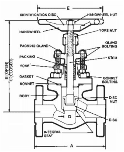
1) Body
2) Spindle wheel and nut
3) Yoke nut
4) Gland packing
5) Gland Bolt
6) Stem
7) Bonnet
8) Disc
9) Disc seat
10) Inlet and Outlet
Maintenance
The gland packing of the valve is subjected to wear and tear and thus needs to be changed after sometime as the sealing quality will reduce.
Moreover, continuous opening and closing of the valve leads to damage to the metal of the valve seat. Lapping paste is applied to the seat to make the surface smooth and remove any clearances.
Uses: Globe valve is used in applications where variable pressure is required in the pipeline such as emergency bilge suction line etc. It can also be used as a non return valve. The type of valve where the disc is not attached to the spindle is called screw down non-return valve. This type of valves is used for preventing back flooding. The type of valve wherein the disc is attached to the spindle is known as screw lift type valve.
Do you have info to share with us ? Suggest a correction

About Author
An ardent sailor and a techie, Anish Wankhede has voyaged on a number of ships as a marine engineer officer. He loves multitasking, networking, and troubleshooting. He is the one behind the unique creativity and aesthetics at Marine Insight.
Latest Marine Technology Articles You Would Like:


- 10 Harmful Effects Of Impure Air On Ship’s Machinery

- 10 Important Things to Check While Starting Fuel Oil Purifier on Ships
- 10 Noteworthy LNG-Powered Vessels
- 10 Points for Efficient Turbocharger Operation On Ships
- 10 Practical Tips to Handle Engine Room Pumps
- 10 Precautions to Take Before Operating Controllable Pitch Propeller (CPP) on Ships


Subscribe To Our Newsletters
By subscribing, you agree to our Privacy Policy and may receive occasional deal communications; you can unsubscribe anytime.