

Oily Water Separator: Construction and Working
As a seafarer on a merchant ship or as a ship manager/owner of a vessel, one of the biggest nightmares is that of any kind of oil pollution accident on a ship.
A ship produces oil and water mixture on a daily basis which needs to be separated from each other before discharging the dirty water out of the ship using equipment such as an oily water separator.
MARPOL has a regulation under ANNEX I, which limits the oil content in the bilge water that a vessel can legitimately discharge into the sea. It is now a requirement for all vessels to have an oil discharge monitoring and control system along with oil filtering equipment known as the Oily Water Separator (OWS).
A ship engineer may work with 5-10 different makes of marine engines, but he/she is more likely to encounter many more types and makes of OWS in his/her career span. Even for PSC inspectors and surveyors, an oil water separator (OWS) has always been a preferred choice of machinery on the ship for inspection. Hence, it is imperative to know and understand the basics of oil and water separator design and how an oil and water separator works.
Related Reading: How to operate an oily water separator?
As the name indicates, the function of an oil-water separator is to separate the maximum amount of oil particles from the water to be discharged overboard from the engine room or cargo hold bilges, oil tanks and oil-contaminated spaces. As per maritime regulations, the oil content in the water processed from the OWS must be less than 15 parts per million of oil.
Related Reading: What is Oil Discharge Monitoring and Control System?
Regulation for Oily Water Separator:
As per Annex 1 of MARPOL under regulation four specified under paragraphs 2, 3, and 6, any direct discharge of oil or oily water mixture into the sea shall be prohibited. The regulation further explains how an oily water mixture can be treated on board and can be discharged out at sea:
Oil Water Discharge Regulation-
For a ship with 400 GT and above, discharge of oil mixture can be done under the following conditions:
1. The ship is en route;
2. The oily mixture is processed through an oil-water separator filter meeting the requirements of regulation 14 of this Annex;
3. After passing the oil-water separator system, the oil content of the effluent without dilution does not exceed 15 parts per million;
4. The oily mixture does not originate from cargo pump-room bilges on oil tankers
5. In an oil tanker ship, the oil-water mixture is not mixed with oil cargo residues
When the ship is plying in the Antarctic area, any discharge into the sea of oil or oily mixtures from any vessel shall be prohibited.
Related Reading: What factors affect separation in oily water separator?
Important Oily Water Separator (OWS) requirement:
- As per the MEPC 107(49), the bilge alarm or an Oil Content Monitor (OCM), which provides for internal recording of alarm conditions, must be certified by an authorized organization
- The OCM provided with the oily water separator must be tamper-proof
- The OCM must activate and sound an alarm whenever freshwater is used for cleaning or zeroing purposes
- Separator capable of achieving 15 ppm on type C emulsion.
- The oily water separator must pass through the minimum discharge limit of 15ppm.
- Sensors and alarms must be installed on the equipment where it can’t be monitored and maintained all the time.
The OWS must only be operated by officers who are familiar with the equipment and who are directly supervised by the Chief Engineer, who bears sole responsibility for its maintenance and operation. When the equipment is not in use, the Chief Engineer is responsible for ensuring that a procedure is in place to lock it out to prevent unauthorized operation with keys in possession of the Chief Engineer.
It should be emphasized that sailing from a port without a functional OWS is unlawful and that appropriate spares for the unit must be carried onboard. The Critical Equipment section contains information on MARPOL equipment.
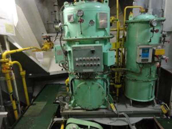
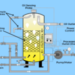
Construction and Working of Oily Water Separator (OWS)
OWS consists of mainly three segments:
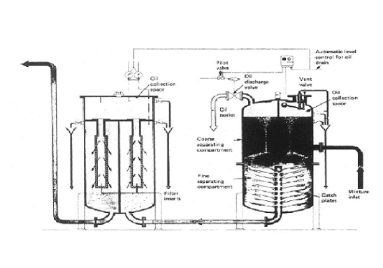
1. Separator unit
- This unit consists of catch plates which are inside a coarse separating compartment and an oil collecting chamber.
- Here the oil has a density which is lower than that of the water, which makes the former rise into the oil collecting compartment and the rest of the non-flowing oil mixture settles down into a fine settling compartment after passing between the catch plates.
- After a period of time, more oil will separate and collect in the oil collecting chamber. The oil content of water which passes through this unit is around 100 parts per million oil.
- A control valve (pneumatic or electronic) releases the separated oil into the designated OWS sludge tank.
- The heater may be incorporated into this unit for smooth flow and separation of oil and water.
- A heater may be incorporated in this unit either in the middle or sometimes in the bottom part of the unit (depending upon the area of operation and capacity of the separator equipment) for smooth flow and separation of oil and water.
- The first stage helps in removing some physical impurities to achieve fine filtration in the later stage.
Related Reading: How Good Bilge Management Practice Help Improve OWS Performance?
2. The Filter unit
- This is a separate unit whose input comes from the discharge of the first unit.
- This unit consists of three stages – filter stage, coalescer stage and collecting chamber.
- The impurities and particles are separated by the filter and are settled at the bottom for removal.
- In the second stage, the coalescer induces a coalescence process in which oil droplets are joined to increase their size by breaking down the surface tension between oil droplets in the mixture.
- These large oil molecules rise above the mixture in the collecting chamber and are removed when required.
- The output from this unit should be less than 15 ppm to fulfil legal discharge criteria.
- If the oil content in water is more than 15 ppm, then maintenance work such as filter cleaning or renewal of filters is to be done as required.
A freshwater inlet connection is also provided to the filter unit to clean and flush the filter. This is usually done before and after the operation of an oil separator unit.
Related Reading: 20 Important Factors For Oily Water Separator Operation On Ships
3. Oil Content Monitor and Control Unit
- This unit functions together in two parts – monitoring and controlling.
- The ppm of oil is continuously monitored by Oil Content Monitor (OCM); if the ppm is high, it will give an alarm and feed data to the control unit.
- The control unit continuously monitors the output signal of OCM, and if an alarm arises, it will not allow the oily water to go overboard by operating a 3-way solenoid valve.
- There usually are three solenoid valves commanded by the control unit. These are located in the first unit oil collecting chamber, second unit oil collecting chamber and one on the discharge side of the oily water separator, which is a 3-way valve.
- The 3-way valve inlet is from the OWS discharge, where one outlet is overboard and the second outlet is to the OWS sludge tank.
- When OCM gives an alarm, the 3-way valve discharges the oily mixture in the sludge tank.

A small pipe connection of fresh water can be provided to the OCM unit for flushing. Whenever this line is in use, an alarm is sounded and recorded in the OCM log, ensuring a record to check the discharge valve was shut during this period.
As in most shipping companies, the OWS is meant to be operated only by the chief engineer, and the training levels on OWS systems for other crew members are found to be very low. The ship operators should ensure onboard guidance and training are included in the training schedule of the ship.
Factors Affecting Separation Of Oil From Bilge Water
Several factors affect the separation of oil from bilge water, such as :
- Density: As water has more density than that oil, it tends to rise
- Adequate Density Difference: Seawater has more density than that freshwater. Thus, by using seawater, we can increase the rate of separation.
- The viscosity of Continues Fluid: we know a less dense fluid with less viscosity offers better conditions for oil to move towards the surface than a dense fluid with more viscosity. Here the viscosity of fresh water is less than that of seawater.
- Temperature: Temperature plays a vital role. It is a significant factor that affects both density and viscosity. When the temperature is low, among fluid particles restricting separation, viscosity is higher.
- Size of particles: The separation of oil from water is directly proportional to the size of oil particles.
Dismantling Procedure for cleaning oil water separator
- First stop the O.W.S Bilge pump
- Top the steam flow to heating coils
- Shut the main overboard valve
- Open vent for both separation and filtration chamber
- Slowly open the drain valve of each section at the bottom
- Oil must be drained out
- All electric and pipe connections must be removed
- Nut and bolts of the top cover of the separation chamber must be opened.
- Baffle plates should be taken out and cleaned with a brush and oil.
- Now open all the nuts and bolts of the top cover of the separation chambers.
- The condition of the coalescer filters must be inspected.
- If necessary, put back a new filter.
- After everything is over, assemble the whole system and fill the O.W.S with fresh, clean water to check for any leakage.
What causes an Oily Water Separator to malfunction?
1. The oil-to-water gravity gradient is the basis upon which the Oily Water Separator works.
Due to the general difference in weight between an oil particle and a particle of water of similar volume, the force exerting on an oil globule to travel in water is proportional to the difference in weight.
A globule’s resistance to mobility is determined by its size and the viscosity of the fluids in which it is contained.
Thus, a high rate of separation is often favoured by
- the large size of the globule.
- Higher system temperature (which affects both the specific gravity difference of the oil and water and the viscosity of the water) and the usage of saltwater.
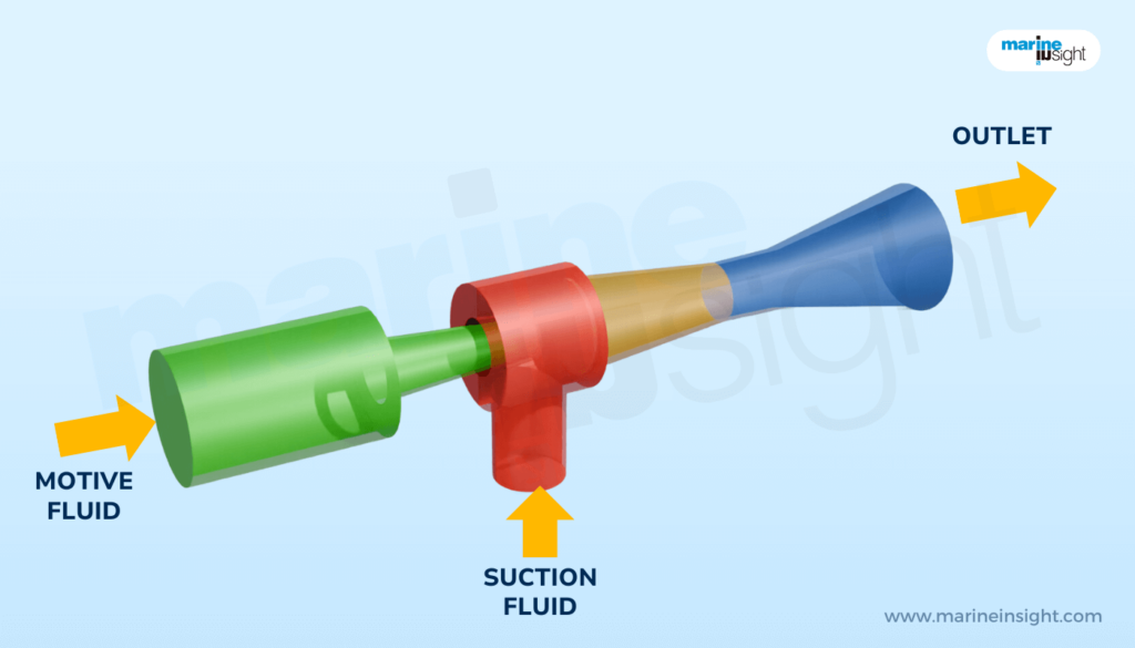
2. Pumping Consideration
An important consideration is to minimize any disintegration of large-sized oil droplets in the feed oil for a separator, which may be greatly impacted by the type and rating of the pump used in the process.
Many bilge pumps are centrifugal, and they are often employed as supply pumps for the separator.
Thus, when the supply is turned on, it creates tiny oil droplets that scatter throughout the water, posing a major threat to the separation’s performance.
A positive displacement pump, such as a slow-running double vane, screw, reciprocating, or gear pump, allows the separator to work considerably better since it does not generate a significant number of tiny droplets. Pumping after the separator may result in a discharge with a concentration of less than 15 ppm without the need for 2nd Stage filters.
As a result of the preceding two arguments, it is clear that even if the separator is properly maintained and operated, the following causes might result in the separator malfunctioning:
- When the separator has an abnormally high throughput.
- Breakdown of wall globules due to extreme rolling and pitching of the ship
- The pump type and rating is not matching, causing too much turbulence
- Due to the high pumping rate, there is turbulence.
Numerous traditional oily water separators cannot split stable emulsions and remove colloidal particles suspended in the water phase. This often leads to equipment failure due to insufficient oil separation below 15 parts per million (ppm) or blockage from excessive solids. An effluent with an oil content of not more than 15 parts of oil per million parts of water by volume may be produced via a combination of a bilge separator, a coalescer, or other techniques.
Recirculation facilities should be installed after and next to the stopping device’s overboard outlet to permit testing of the 15 ppm bilge separator system, including the 15 ppm bilge alarm and the automated stopping mechanism, with the overboard discharge locked.
The influence of bilge water containing cleaning chemicals is one of the primary reasons for oily water filtration system failure. Cleaning fluids based on detergents may form chemically stabilized oil emulsions that cannot be separated on board ships just by gravity. Avoiding the use of surfactant-based cleaning chemicals is the greatest strategy to optimize the effectiveness of oily bilge water separation equipment.
Maintenance of Oily Water Separator
To remain in excellent operating condition, an oily water separator must be properly and routinely maintained. When these devices are not drained and cleaned consistently, oils and other debris clog them and render them inoperable. This may result in oil levels in the discharged water exceeding the effluent limitations mentioned.
Oily water separator models that are elevated above the ground are considerably simpler to clean since everything is easily accessible. This is because there are no restricted places, and plates may be removed, cleaned, and changed. All forms of above-ground structures may be maintained from the ground. Additionally, solid waste may be conveniently evacuated via a big hole at ground level.
When employing a below-ground oil-water separator, it is essential to adhere to a tight maintenance plan. It is more probable that you will overlook cleaning the unit since it is buried in the ground. These are the oil-water separator maintenance methods to follow.
After a month of usage, do the following checks and cleanings on the inlet area:
- Turn off the unit’s supply of water.
- Open the cover of the unit.
- If there is any oil present, remove it and dispose of it in accordance with corporate and legal regulations.
- Water should be drained from the separator.
- Take a measurement of the depth of the residual solids and record it. In the future, this will serve as a foundation for planning maintenance and cleaning tasks.
- Get rid of the solids if required.
The media plates will need to be cleaned once all of this has been completed. They may be cleaned either inside or outside the unit. Insert a low-pressure hose in between the plate gaps on the plate packs to clean them without dismantling them. Remove any debris drained from the plates by draining it down the hopper outlet.
When cleaning the plates outside of the oil-water separator, use a low-pressure hose to rinse them off, taking particular care not to get any of the discharge on the ground where it might contaminate groundwater. Getting rid of the accumulated sludge and oil is the only thing that’s required.
To make sure that the tank is safe, check it for damage and fix the internal coating if it needs to be done. Simply re-insert the plate packs into the separator in the same order as they were removed in order to restart the machine. Make sure that they are firmly attached to the device so that they don’t fly away when it restarts. Depending on the unit’s use and the quantity of oil and other debris collected, maintenance should be performed on a regular basis by a skilled specialist.
References
Introduction to Marine Engineering– By D.A Taylor
Disclaimer: The authors’ views expressed in this article do not necessarily reflect the views of Marine Insight. Data and charts, if used in the article, have been sourced from available information and have not been authenticated by any statutory authority. The author and Marine Insight do not claim it to be accurate nor accept any responsibility for the same. The views constitute only the opinions and do not constitute any guidelines or recommendations on any course of action to be followed by the reader.
The article or images cannot be reproduced, copied, shared or used in any form without the permission of the author and Marine Insight.
Do you have info to share with us ? Suggest a correction

About Author
An ardent sailor and a techie, Anish Wankhede has voyaged on a number of ships as a marine engineer officer. He loves multitasking, networking, and troubleshooting. He is the one behind the unique creativity and aesthetics at Marine Insight.
Latest Marine Technology Articles You Would Like:
- 10 Oily Water Separator (OWS) Maintenance Tips Every Ship Engineer Must Know

- How to Operate an Oily Water Separator (OWS) on Ship?
- 20 Important Factors For Oily Water Separator Operation On Ships
- Oily Water Separator: Construction and Working
- What Factors Affect Separation in Oily Water Separator on Ships?

Subscribe To Our Newsletters
By subscribing, you agree to our Privacy Policy and may receive occasional deal communications; you can unsubscribe anytime.
sir can you please elaborate how to test a 15ppm monitor?
Could you please give a reason as why 15ppm is chosen as the maximum figure for Oily Water Separator?
Naveen Rajeev,
The procedures for testing the monitor are detailed in the manufactures technical manual. The OWSs I have experience utilize a photo sensor that measures the amount of light hitting it. When oil or sediment travels between the light and the photo sensor, it reduces the amount of light hitting the sensor and causes the monitor to display a PPM of contaminate in the water. On the OWSs I have seen, the manufacture provides plastic test trips that have been gauged to simulate oily water contamination. This test trip is placed between the light and the photo-sensor through an inline access point. The monitor should display the predetermined reading when this test is conducted. Ships also send these sensors out to be tested and calibrated on a scheduled basis.
in the figure at second stage there are two sensor connected to control box what is the function of that two sensor
Why oil-water separator, even if well maintained and correctly operated may not function properly?
can we use oily water separator in place of purifier or vice versa?
@Gulshan Kumar
Absolutely not. The Basic purpose of both the machines are different and the amount of OIL they handle is the key. OWS is used for removing small amount oil from a large quantity of water. The difference in densities of bilge water (which is processed in OWS) is small compared to the feed or purifier.
Centrifuges, however, used to do opposite task- remove water from a larger oil quantity. They also need to remove solid impurities and sludge.
Can you please tell me which pump is used in oily water separator along with the reason
OWS should be annual service by shore or not.
@Sinthu: The Oil content monitor needs to be serviced by shore technician
Hi,
I can’t be sure difference usage of OWS in and out of special areas for oil tankers.
Please, can you expain it?
Hi
Please check this article for the requirements – https://www.marineinsight.com/maritime-law/marpol-annex-1-explained-how-to-prevent-pollution-from-oil-at-sea/
Dear Sir,
Please explain why at 3 way valves there are 2 go collecting chamber?
क्या आप मुझे बता सकते हैं कि किस कारण से ऑयली वाटर सेपरेटर में कौन सा पंप इस्तेमाल किया जाता है