

Understanding The Design of Liquefied Gas Carriers
In our previous article we described design of different types of tankers. In this article we will understand types and design of liquified gas carrier vessels.
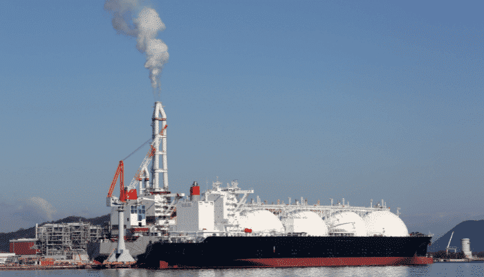
Ships that are designed to carry liquefied gas have become more significant and increased in number in the recent years, with the increasing need for alternative fuel.
The two main types of liquefied gas carriers are
- LPG (Liquefied Petroleum Gas) Carriers, and
- LNG (Liquefied Natural Gas) Carriers.
To understand the design characteristics of these two types of ships, we first need to know a few notable details about the composition and properties of LPG and LNG.
Liquefied Petroleum Gas (LPG):
Petroleum hydrocarbon products such as Propane and Butane, and mixtures of both have been categorised by the oil industry as LPG. It is widely used in domestic and industrial purposes today. The most important property of LPG is that it is suitable for being pressurised into liquid form and transported. But there are conditions related to pressure and temperature that need to be maintained for the above to be carried out without posing threat to life, environment, and cargo. At least one of the following conditions need to be complied with, for transportation of LPG:
- The gas should be pressurised at ambient temperature.
- The gas should be fully refrigerated at its boiling point. Boiling point of LPG rangers from -30 degree Celsius to -48 degree celsius. This condition is called fully-refrigerated condition.
- The gas must be semi-refrigerated to a reduced temperature and pressurised.
We will see, at a later stage, how the above conditions affect the design of different types of LPG tankers.
Other gases such as ammonia, ethylene and propylene are also transported in liquefied form in LPG carriers. Ethylene, however, has a lower boiling point (-104 degree Celsius) than other LPGs. Hence it must be carried in semi-refrigerated or fully-refrigerated conditions.
Liquefied Natural Gas (LNG):
Natural gas from which impurities like sulphur and carbon-dioxide have been removed, is called Liquefied Natural Gas. After removal of impurities, it is cooled to its boiling point (-165 degree Celsius), at or almost at atmospheric pressure. Note here, that unlike LPG, LNG is cooled to low temperatures but not pressurised much above atmospheric pressure. This is what makes the design of LNG carriers slightly different from LPG carriers. LNG, at this condition is transported as liquid methane.
Design of Different Types of Gas Carriers:
In this article, we will understand the general arrangement, and other design details of gas carriers as and when we look into the different types of vessels based on their functionality and type of cargo being carried. The most important feature of gas carriers is the cargo containment system. It is according to this criteria that LPG carriers are categorised into types.
Integral Tanks:
These are the tanks that form a primary structural part of the ship and are influenced by the loads coming onto the hull structure. They are mainly used for cases when LPG is to be carried at conditions close to atmospheric condition, for example – Butane. That is because, in this case, there are no requirements for expansion or contraction of the tank structure.
Independent Tanks:
These tanks are self-supporting in nature, and they do not form an integral part of the hull structure. Hence, they do not contribute to the overall strength of the hull girder. According to IGC Code, Chapter 4, independent tanks are categorised into three types:
Type ‘A’ Tanks: These tanks are designed using the traditional method of ship structural design. LPG at near-atmospheric conditions or LNG can be carried in these tanks. The design pressure of Type A tanks is less than 700 mbar. The following figures show the general arrangement of a liquid methane carrier with Type ‘A’ tanks.
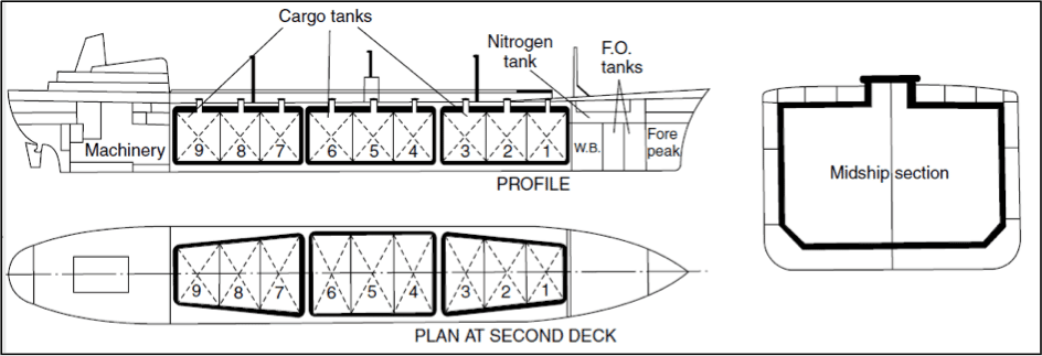
The general arrangement of an LPG ship is almost same as that of an oil carrier, with the cargo tanks spread over a certain length forward and abaft the midship, the machinery and superstructure at the aft. A forecastle is fitted at the bow so as to prevent green waters on deck. Ballast water cannot be carried in the cargo tanks, hence spaces for ballast are provided by incorporating double hull spaces (note the double hull in the midship section), bilge and upper wing tanks.
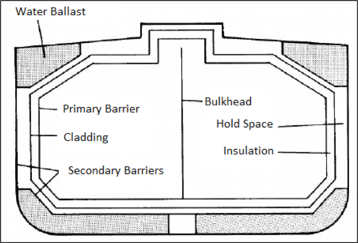
The most notable and distinguishing feature of Type ‘A’ tanks is that the IGC Code specifies that Type ‘A’ tanks must have a secondary barrier to contain any leakage for at least 15 days. The secondary barrier must be a complete barrier of such capacity that it is sufficient to contain the entire tank volume at any heel angle. Often, this secondary barrier comprises of the spaces in the ship’s hull as shown in the figure below.
One important question that could arise, here, is that the tank in the midship section view seems to be an integral part of the hull. Why then, is this type of tanks categorised under Independent Tanks? To find the answer we need to have a closer look at how the tank is installed in the hull.
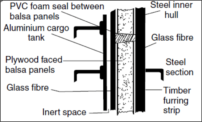
The above figure shows how the aluminum tank structure is not integrated to the inner hull of the methane carrier by means of any metal contact. The inner hull plating and aluminum tank plating are separated by layers consisting of timber, glass fibre, and balsa panels for insulation from external temperatures. The balsa panels are held together by plywood on both faces which are sealed using PVC foam seals. An inert space of 2 or 3 mm separates the inner glass fibre layer from the aluminum tank plate. This space is provided for insulation and also allows expansion and contraction of the tank structure. This type of non-welded integration makes this tank structurally independent in nature.
Type ‘B’ Tanks: The concept behind the design of such tanks is to have such a structure in which a crack can be detected long before the actual failure. This allows a time margin before the actual failure occurs. The methods used for design of such tanks include determination of stress levels at various temperatures and pressures by first principle analyses, determination of fatigue life of tank structure, and study of crack propagation characteristics. This enhanced design of such tanks requires on a partial barrier, that we will look into, soon.
The most common arrangement of Type ‘B’ tank is Kvaerner-Moss Spherical Tank, as shown below in Figure 4.
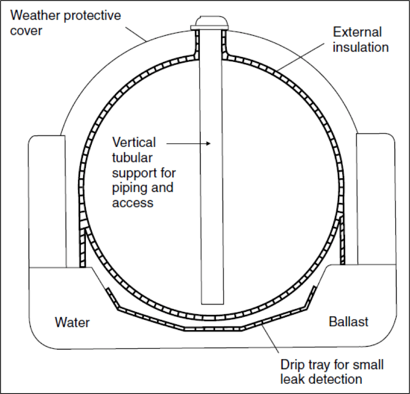
The tank structure is spherical in shape, and it is so positioned in the ship’s hull that only half or a greater portion of the sphere is under the main deck level. The outer surface of the tank plating is provided with external insulation, and the portion of the tank above the main deck level is protected by a weather protective layer. A vertical tubular support is led from the top of the tank to the bottom, which houses the piping and the access rungs.
As evident from the layout, any leakage in the tank would cause the spill to accumulate on the drip tray below the tank. The drip pan and the equatorial region of the tank are equipped with temperature sensors to detect the presence of LNG. This acts as a partial secondary barrier for the tank.
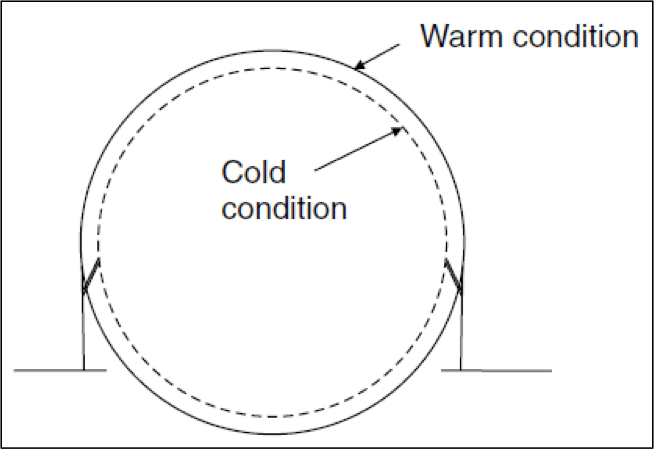
LNG is usually carried in this type of tanks. A flexible foundation allows free expansion and contraction according to thermal conditions, and such dimensional changes do not interact with the primary hull structure, as shown in Figure 5.
The following are the advantages of Kvaerner-Moss Spherical tanks:
- It enables space between the inner and outer hull (see Figure 4.) and this can be used for ballast and provided protection to cargo in case of side-ward collision damages.
- The spherical shape allows even distribution of stress, therefore reducing the risk of fracture or failure.
- Since ‘Leak before Failure’ concept is used in the design, it presumes and ensures that the primary barrier (tank shell) will fail progressively and not catastrophically. This allows crack generation to occur before it propagates and causes ultimate failure.
Type ‘C’ Tanks: These tanks are designed as cryogenic pressure vessels, using conventional pressure vessel codes, and the dominant design criteria is the vapour pressure. The design pressure for these tanks is in ranges above 2000 mbar. The most common shapes for these tanks are cylindrical and bi-lobe. Though Type ‘C’ tanks are used in both, LPG and LNG carriers, it is the dominant design in LNG carriers.
The following figures show the arrangements of cylindrical and bilobe tank arrangements in midship view. The cylinders can be either vertically or horizontally mounted, depending on the dimensions and spatial constraints of the ship. Note, in Figure 6, that the space between the two cylinders is rendered useless. Due to this, the use of cylindrical tanks is a poor use of the hull volume. In order to circumvent this, the pressure vessels are made to intersect, or bilobe tanks are used (Figure 7).
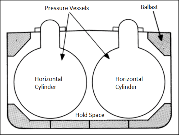
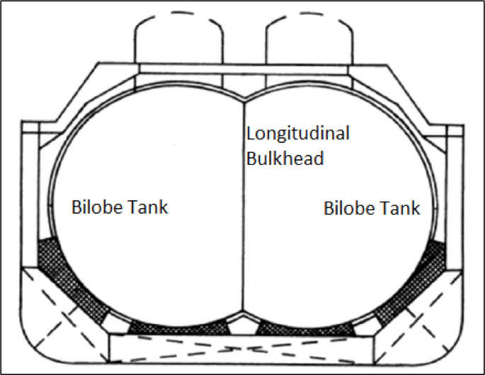
These types of tanks do not require a secondary barrier. Rather, to detect the leakage of cargo from the tanks, the hold space (refer to Figure 6) is filled with inert gas or dry air. Sensors placed in the hold space can detect the change in composition of the inert gas or dry air due to fuel vapour, and leakages can hence be detected and prevented. Bilobe tanks at the forward end of the ship are tapered at the end.
Membrane Tanks:
Unlike independent tanks, membrane tanks are non-self-supporting structures. Their primary barrier consists of a thin layer of membrane (0.7 to 1.5 mm thick). The membrane is supported to the inner hull structure through an insulation that can range upto 10 mm thickness as per IMO IGC Code. Due to their non-self-supporting nature, the inner hull bears the loads imparted onto the tank. This way, the expansions and contractions due to thermal fluctuations are compensated by not allowing the stress to be taken up by the membrane itself. Membrane tanks are primarily used for LNG cargo.
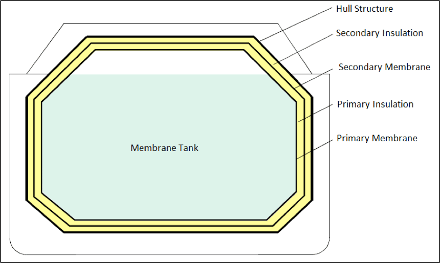
Often, there are two layers (primary and secondary) of insulation and membranes placed alternatively. The most common types of membtane tanks are the ones designed and developed by two French companies Technigaz and Gaz Transport. The Tehnigaz system makes use of a stainless steel system that is constructed with corrugated sheets in such a way that one sheet is free to expand or contract independent of the adjacent sheet. The Gaz Transport system uses Invar as the primary and secondary membranes. Invar has low coefficient of thermal expansion, which makes corrugations unnecessary. The insulation is usually made of materials like Reinforced Polyurethane. In GTT membrane tanks, the primary membrane is made of Corrugated SUS 304, and the secondary membrane is made of Glued Triplex. Figure 8 illustrates the anatomy of twin-membrane tanks.
Some of the advantages of membrane tanks are as follows:
- They are generally of smaller gross tonnage, that is the space occupied within the hull is lower for a given cargo volume.
- Due to the above reason, maximum space in the hold can be used for cargo containment.
- Since the height of tanks above the main deck is significantly lesser compared to the cases of Moss tanks, membrane tanks provide allow visibility from the navigational bridge. This also allows a lower wheelhouse. This can be compared in Figures 10 and 11.
LPG Containment Systems:
Unlike LNG, LPG cargo requires storage at conditions that are different from atmospheric conditions. The LPG containment systems are classified into three types, and each LPG carrier is designed according to any one of them.
Fully Pressurized Tanks:
Propane, Butane and Anhydrous ammonia are carried in fully pressurized tanks. The capacity of these tanks is usually less than 2000 cubic meters. They are usually uninsulated cylindrical pressure vessels that are arranged partly below main deck level. Since these are Type C tanks, they often prevent complete utilization of under deck volume.
Semi Pressurized or Semi Refrigerated Tanks:
Though the cargo carried by semi-pressurized ships are same as that of fully-pressurized ships, the volume of semi-pressurized ships is about 5000 cubic meters. These use Independent Type C tanks, and are constructed with ordinary grades of steel. The outer surface of these tanks are insulated, and refrigeration or reliquefication plants are installed on these ships to maintain the working pressure of the cargo. The most ommon types of tanks used for this purpose are cylindrical and bi-lobe type.
Fully Refrigerated Tanks:
Fully Refrigerated gas carriers have a capacity of 10,000 to 1,00,000 cubic meters. The ships in the smaller size range are used to carry multiple types of cargo, whereas the larger ones are designed for a single type of cargo to be transported on a permanent route. The tanks used for this purpose is usually Type ‘A’ prismatic tanks that are sloped at the top end to reduce free surface effect, and sloped at the bottom to suit the shape of the bilge structure. They are usually divided longitudinally by a liquid-tight bulkhead, in order to reduce free surface effects further. These tanks are constructed with notch ductile steel, in order to be provided with maximum notch toughness at temperatures as low as -48 degrees Celsius, at which cargo like Propane is transported.
The number of gas carriers have increased drastically over the last ten years, owing to the increasing need for alternative fuel. These are usually high speed ships with fine hull-form, which makes it possible for extensive research opportunities to improve on hull efficiencies in order to achieve more power efficiency. A lot of research is also being carried out to design advanced cargo containment systems and concepts of adjoining bunkering systems are being developed by various countries that are opening themselves to extensive use of natural gas. Today, not all shipyards are equipped to design and build specialised ships like LPG and LNG carriers. This leaves a wide scope for designers and shipbuilders to develop skills and infrastructure to specialise in building these ships.
Do you have info to share with us ? Suggest a correction


Latest Naval Arch Articles You Would Like:
Subscribe To Our Newsletters
By subscribing, you agree to our Privacy Policy and may receive occasional deal communications; you can unsubscribe anytime.
What is the thickness of secondary barrier in membrane tanks ? Is it same as primary barrier of 0.7-1.5 mm thickness ?
Great post! Have nice day ! 🙂 gzmjh
Good day. thank you for the informative article. Anyhow can you help me where i can find a training center that offer Cargo reliquefaction system, operation and maintenance of the equipment. any suggestion is highly appreciated.
@Shams: Do check Kongsberg Maritime training as they provide it in cargo re-liquification.
What are the typical dimensions for an oil cargo tank?
Hi…Good day…Very informative article…Could you please get me similar idea on ‘iron concentrate slurry ship’ design…Is any slurry vessel operational today…Thanks
Very good publication. Many thanks and I realy appreciate.
Boiling point of ethylene is -104⁰C not -140⁰C mentioned in the article. I am sure the authors will agree on the importance of accuracy.
Thank you Sami for pointing this out. It was an honest mistake (Typo) from our side.
The same has been corrected.
Glad you liked it. Please do share and support