

Types of Vibrations On Ships – Hull Girder Vibration
In our previous article on ship vibrations, we discussed machinery vibrations i.e. different types of machinery vibrations, their excitation sources, and design methods to reduce each type of such vibration. One very notable aspect of that article is, we have till now, discussed the effect of those excitation sources on machinery components (e.g. on the main propulsion system); but the overall effect of the excitations is also propagated to the hull structure. Such vibrations are called Hull Girder Vibrations or Global Vibrations, and they will be dealt with in this article.
To start with, we will deal with the different sources of excitation for hull girder vibration.
Excitations for Hull Girder Vibration:
1) Excitation – Low Speed Main Diesel Engine:
A low speed main diesel engine has always been the primary source of vibrations in the hull girder. The excitation from diesel engine can be considered to comprise of three periodic forces and three periodic moments that act on the foundation of the engine. Among the three periodic forces, the force along the axis of the shaft is cancelled out by the periodic thrust. What remains, are the other two. They can be categorised as:
a) Gas Pressure Forces: The forces exerted due to the gas pressures that occur at various stages of one revolution of the engine. These forces are also called Guide Force Couples. They act on the crosshead of the engine, and are a result of transverse reaction forces due to firing orders, depending on the number of cylinders. The nature of the guide force couples are shown in Figure 1. Note how the forces result in couples, before we discuss the nature of vibration resulting from this.
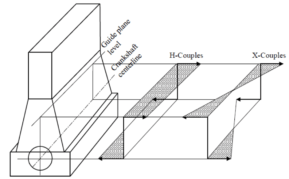
Now, an H-Couple would result in a periodic motion of the engine, where the topmost part of the engine is in a phase opposite to the part in contact with the engine foundation. But an X-Couple would result in the forward end of the engine being in a phase opposite to that of the aft end of the engine. When the frequency of these forces are in the range of the natural frequency of the engine foundation, the foundation resonates, resulting in local vibrations in the engine room bottom structure.
Thus, to prevent this motion, lateral stays or top bracings are used to connect the top structure of the engine to the hull girder. Sometimes, at earlier stages of structural design, a redesign of the engine foundation is recommended so as to change the stiffness of the structure.
b) Inertia Forces: The rotating parts of a low speed main diesel engine are usually of high mass. Therefore, the acceleration of the reciprocating engine parts result in the generation of high inertia forces.
Having dealt with the periodic forces, the other aspect of main engine excitation is that of Periodic Moments. In an internal combustion engine, the time taken by the piston to travel from the Top Dead Centre (TDC) to the Bottom Dead Centre (BDC) is not same as the time taken by the piston to travel from BDC to TDC. This can be mathematically proved, but is not within the scope of this article. What is important to note here is the fact that, in one complete revolution, the time taken in each half is different. This gives rise to Second Order Vertical Moments (M2V).
A Fact: These moments are periodic, and have a frequency twice that of the RPM of the engine.
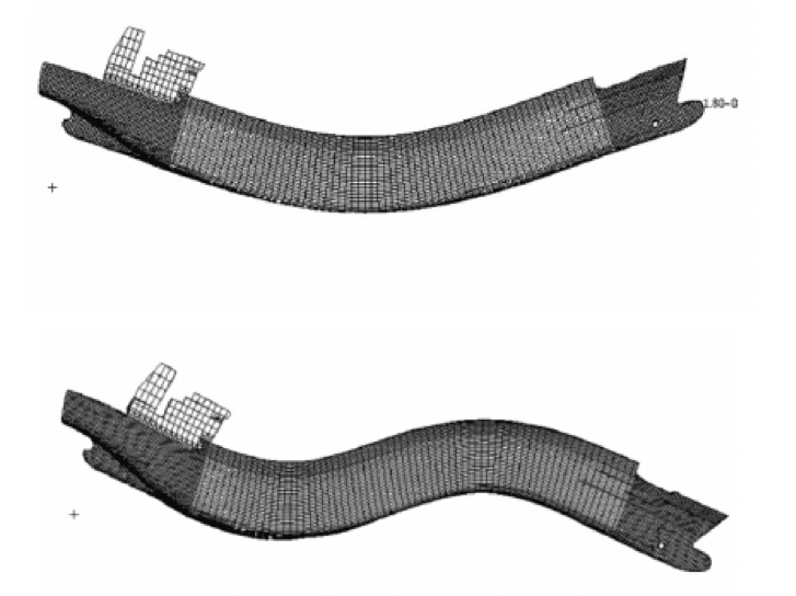
In case of a marine diesel engine with six or more cylinders in service, the second order vertical moment of the engine plays a very important role in determining the possibility of hull girder vibration. That is because, it has been found that the first three or four natural modes of vertical vibration of the hull girder can be as high as twice the RPM of the engine. Now, if you look back to the above fact, it would imply that the frequency of second order vertical moments of the main engine is usually within the range of first three to four natural modes of vertical vibration of the hull girder. Thus arises a chance of resonance, resulting in vertical vibration of the hull girder. The first two nodes of vertical vibration of hull girder are shown in Figure 2.
In order to avoid this, the designer must request the values of second order vertical moments of the engine from the engine manufacturer. Once that is done, the Power Related Unbalance (PRU) is calculated, which helps the designer to decide the course of action to be followed.

The PRU value obtained will give the designer an idea if there is a need to add moment compensators to the engine. Moment compensators (manufactured by the engine manufacturer) are additional reciprocating parts that are tuned in such a way that the residual moments generated by them is cancelled by the second order vertical moment of the main engine.
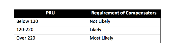
The above table is recommended by classification societies, and helps in accessing the requirement of compensators. However, if this analysis is being done in a very initial stage of the design, the designer might as well opt for a change in engine selection.
2. Excitation – Hull Wake:
It has already been discussed in the previous part of this series, how varying wake on the propeller due to the stern contour of the hull results in propeller induced vibrations.
Hull wake is not an adjustable factor in the later stages of design, once the hull form, stern contour, and number of screws have been fixed. This can be altered only at the hydrodynamic stages of design, using hydrodynamic software that analyse the flow of water around the hull.
3. Excitation – Propeller:
There are two types of excitation caused by the rotation of a propeller, and they are as follows:
a. Alternating Thrust: This results in longitudinal vibration of the propulsion system, and has been discussed in detail in the first part of this series.
b. Propeller Cavitation: Propeller cavitation results in formation of bubbles that implode on the propeller blade. Usually, a propeller blade does not cavitate at every point in one revolution. It cavitates only at points where the total pressure on the blade falls below the vapour pressure of sea water. What results, the generation of a periodic excitation force due to implosion of the bubbles. So design of propeller must take into account the possibility of cavitation at various speeds.
Often, propeller blades have a certain skew angle to reduce cavitation. A skew does so by preventing the entire blade from passing through a region of cavitation at once. Due to the skew angle, each section of the propeller blade passes through a cavitating region gradually, thereby preventing the entire blade from cavitating.
c. Vertical Pressure Forces on the Stern: Due to the rotation of the propeller, vertical pressure forces are exerted on the stern of the ship. By now, it should be easy to imagine that the frequency of these pressure forces will be same as the excitation frequency of the propeller (i.e. RPM x Number of blades). This kind of excitation is more common in ships having long overhanging sterns, and vibration is usually felt in the aft section of the ship.
An Important Tip: While deciding the number of propeller blades for a particular ship, a designer should first know the number of cylinders in the main engine. The number of cylinders and the number of blades should not be integral multiples of a number. For example, for a ship using a main engine with four cylinders, a six blade propeller is strictly avoided because the propeller excitation frequency depends on the number of blades, and the engine frequency depends on the number of cylinders. If both parameters are integral multiples of a number, resonance is likely. So, by practice, a main engine with four cylinders will be used with either a three-bladed or five-bladed propeller.
Superstructure Forward and Aft Vibration:
Since the time when length of cargo ships began to increase drastically, the engine room of most ship types was shifted aft, from midships, in order to reduce the shafting length. More length also meant requirement of higher longitudinal strength. In order to do that, discontinuities had to be shifted away from the midship. As a result, most superstructures had to be shifted towards the aft. The navigation deckhouse required to be at a certain height from the main deck so as to provide sufficient view forward of the ship’s bow. Also, the deckhouse structure is generally located on the engine room cavity, which makes it difficult to achieve sufficient stiffness of the structure. Due to the closer proximity of the superstructure to the propeller, and the light weight of the top structures of the deckhouse, propeller-induced superstructure vibration has become an important aspect of ship vibrations.
There are two types of motions related to superstructure vibrations, and they are:
- Rocking
- Bending
Detailed analysis carried out by Hirowatari and Matsumoto on different types of superstructure, now enables the determination of torsional and bending stiffness of a superstructure required to maintain rocking and bending motions of the superstructure within safe limits. The main excitations of superstructure vibration are propeller induced forces and low speed diesel engine. In vibration analyses, superstructure vibration is treated separately from hull girder vibration, and methods to carry out these calculations are recommended by classification societies.
Hull Girder Vibration Analysis Using Hull Resonance Diagram:
This is one of the most widely used methods to check the possibilities of hull girder vibration. In this, not only the vertical modes of hull girder vibration are taken into account, but also the horizontal (transverse) and torsional modes are considered. First, let us understand the fundamental use of a Hull Resonance Diagram.
A Hull Resonance Diagram is prepared by a ship designer for each ship, in order to check if the hull girder vibration modes are being excited by the main engine and propeller. Using this analysis, the designer is able to check if the propeller RPM required to provide the thrust does not result in hull girder vibration. Hull Resonance Diagram is also used in determining the number of propeller blades required so as to prevent resonance.
As we go through the process of understanding the process behind preparing a Hull Resonance Diagram, refer to Figure 3.
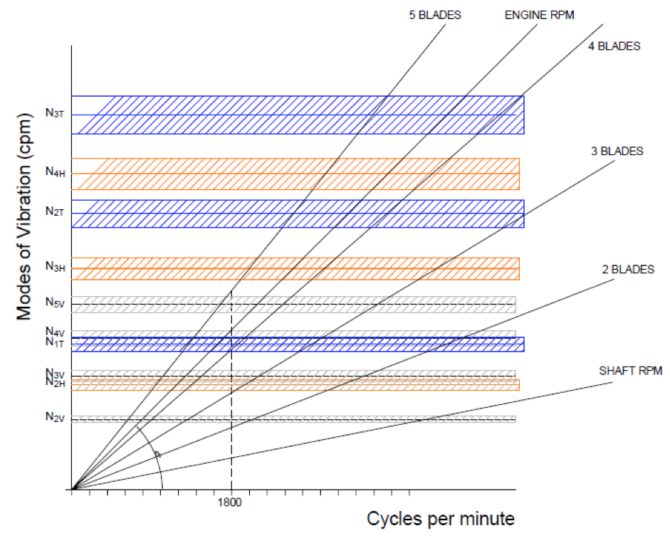
The vertical axis represents the values of natural frequencies of vertical, horizontal, and torsional vibration of the hull girder. The designer must have the midship section drawing obtained from scantling calculations. Once that is prepared, the values in the vertical axis can be calculated using class recommended formulae. Here,
N2V , N3V , N4V , N5V are the second, third, fourth and fifth modes of vertical hull girder vibration. (Shown in Light Blue)
N1T , N2T , N3T are the first, second, and third modes of torsional hull girder vibration. (Shown in Violet)
N2H , N3H , N4H are the second, third, and fourth horizontal hull girder vibration. (Shown in Orange)
Once these values are obtained, they are plotted on the axis, and a tolerance of 5 percent is taken for factor of safety. So, the shaded bands in the diagram represent each mode with 5 percent tolerance. Our aim now, is to ensure that the Propeller RPM do not lie within any of these bands.
A line is drawn at 45 degree angle to the horizontal. This line represents the Engine RPM. For this project, the operating RPM of the engine was 1800. Depending on the Gear Ratio, the slope of the Engine RPM line is divided to obtain the Shaft RPM line. Now, the line for a propeller with two blades would have a slope two times the slope of the Shaft RPM (Because Propeller Excitation Frequency = RPM x No. of Blades), and so on. So, lines are drawn for propellers with three, four, and five blades.
The following conclusions can be made out of the diagram now:
- Two Bladed propeller: Though at 1800 RPM, the line of the two bladed propeller does not intersect any of the bands, it cannot be used because two blades are not efficient from hydrodynamic point of view.
- Three Bladed Propeller: It is very clearly visible that at 1800 RPM, the line for three bladed propeller intersects the bands of N2H and N3V. This means, if an engine rated at 1800 RPM is used in combination with a three bladed propeller, it would result in Second Mode of Horizontal Vibration and Third Mode of Vertical Vibration of the hull girder, which would be catastrophic. Thus, the option for a three bladed propeller is rejected.
- Four Bladed Propeller: At 1800 RPM, the line for four bladed propeller intersects the N1T and N4V Thus, this option stands rejected.
- Five Bladed Propeller: At 1800 RPM, the line of five bladed propeller does not intersect any of the bands. This means, for an engine rated at 1800 RPM, a five bladed propeller would not excite any of the modes of hull girder vibration. It is after this, that a five bladed propeller can be deemed suitable for this particular ship.
Though the above method may seem to provide accuracy in predicting hull girder vibrations, they are still preliminary in their scope of application because of various assumptions taken in formulating the empirical formulae behind the Hull Resonance Diagram. A better result can be obtained by conducting vibrational analyses both on a local and global level using Finite Element Models of the ship, which is a method mandatorily recommended by every classification society today.
Do you have info to share with us ? Suggest a correction


Latest Naval Arch Articles You Would Like:
Subscribe To Our Newsletters
By subscribing, you agree to our Privacy Policy and may receive occasional deal communications; you can unsubscribe anytime.
Hi
An informative article that will be very useful.
I am a P.G student and working on vibration analysis of drive panels that is mounted in ships.
Can you help me on this with some support.
I need some clarifications on how to start working for this project.
1. What type literature survey has to be made?
2. What will be the excitation forces have to be considered when analyzing a cabinet inside the ship?
3. Is that Ship vibration will be the same for the cabinet present inside the ship?
Hi
Thanks a lot for the article.
I hope that you sometimes answer questions to your articles, since I don’t fully understand the Hull Resonance Diagram (Figure 3) and your explanation to it. Well, I will try 🙂
The intersection between the “3 Blades” line and the 1800 vertical line is just below the N2H and N3V band.
The intersection between the “5 Blades” line and the 1800 vertical line is just above the N5V band.
If they are both not inside the band, why are 3Blades bad and 5 Blades good?
Hi Sir,
It is very helpful article.
N2V , N3V , N4V , N5V Can these values be extracted using FE models and softwares?