

Ship Stability – Introduction to Hydrostatics and Stability of Surface Ships
The concept of hydrostatics and stability can be deemed as one of the most important areas of focus in ship design and operation, not only to ensure the safety of the ship, cargo, crew and passengers but also to enable proper conditions for completion of all the processes on a ship.
This series of articles will first discuss the concept of hydrostatics of a ship and slowly transition into an introduction of ship stability. Once that is done, we will see how the concepts are applied in real-time and probable situations to analyse the stability of the ship, how a designer applies concepts of hydrostatics and stability to develop a hull form, and so on.
Ship Hydrostatics:
Some characteristic parameters calculated for a floating ship, which can either directly be used to comment on the nature of stability of the ship or be used to evaluate other stability parameters, are called ship hydrostatics. For a designer to be able to develop a hull form, or a ship’s captain to understand the stability parameters, it is important for both to be able to understand the meaning and practical significance of each hydrostatic parameter of a surface ship. We will first list the hydrostatics of a surface ship, and then move on to define them.
- Vertical, Longitudinal and Transverse Center of Gravity
- Vertical, Longitudinal and Transverse Center of Buoyancy
- Mass Displacement (Δ)
- Volume Displacement (∇)
- Longitudinal and Transverse Centre of Floatation
- Metacentre
- Metacentric Height
- Metacentric Radius
- Moment to Change Trim 1 cm (MCT)
- Tonnes per cm Immersion (TPC)
To understand hydrostatics, we need to acquaint ourselves with a few basic ship terminologies that often appear in the process of understanding and evaluating of hydrostatics and stability parameters of a surface ship. Follow the figure below with reference to the terminologies described underneath.
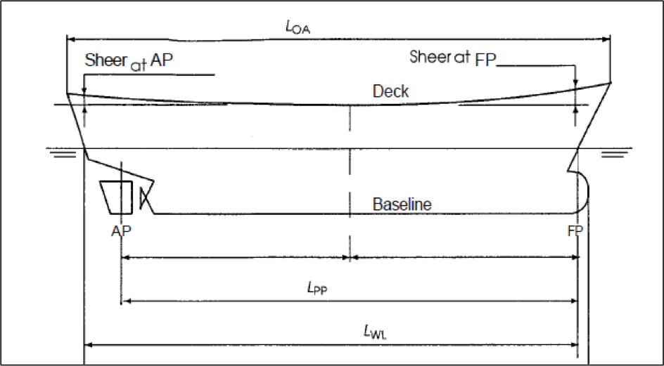
- Forward Perpendicular: The perpendicular drawn at the point where the bow of the ship meets the waterline while it floats at design draft, is called Forward Perpendicular (FP).
- Aft perpendicular: The perpendicular drawn through the rudder stock is called the Aft Perpendicular (AP).
- Length between Perpendiculars (LPP or LBP): The longitudinal distance between the forward and aft perpendiculars is called length between perpendiculars.
- Length of Waterline (LWL): The length of the ship’s hull intersecting the surface of the water is called Length on Waterline.
- Length Overall (LOA): The maximum length from the forward most point of the ship’s hull to the aft-most point, is called Length Overall.
- Keel (K): The keel is the lowermost point of the ship at any point of its length. The baseline of a ship is the longitudinal line that runs along the keel.
Before we move on, another important technique used in the calculation of ship hydrostatics and stability parameters is that of stations. A ship’s hull is longitudinally divided into stations, which are nothing but specified positions along the length of the ship with reference to the aft perpendicular which is numbered as zero station.
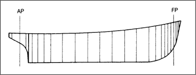
The distance between each station remains constant in the vicinity of the midship where a significant parallel mid-body shape prevails. But as we move towards the aft or forward, the shape of the hull attains a complex geometry, and hence for better results of analyses, the distance between the stations are reduced.
1. Center of Gravity (CG):
The longitudinal position of the CG with respect to any reference point on the ship is called the longitudinal centre of gravity (LCG). Usually, the reference point for locating the LCG is either of the forward or aft perpendiculars.
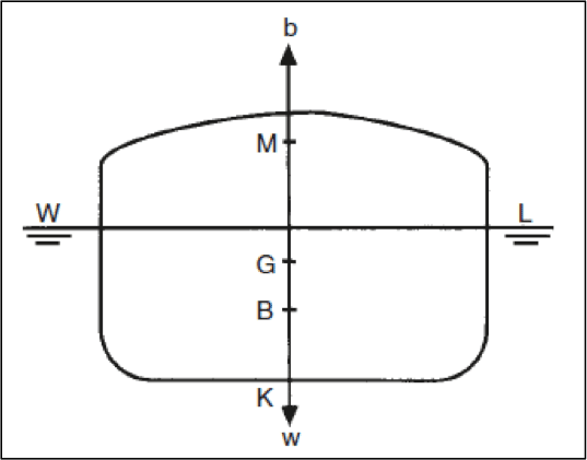
The vertical distance (along the ship’s centerline) between the keel and the centre of gravity is expressed as ‘KG’, as shown in Figure 2.
2. Center of Buoyancy (CB):
The longitudinal position of the centre of buoyancy with respect to any reference point on the ship is called the longitudinal centre of gravity (LCB). Usually, the reference point for locating the LCG is either of the forward or aft perpendiculars.
The vertical distance (along the ship’s centerline) between the keel and the centre of buoyancy is expressed as ‘KB’, as shown in Figure 3.
3. Metacenter (M):
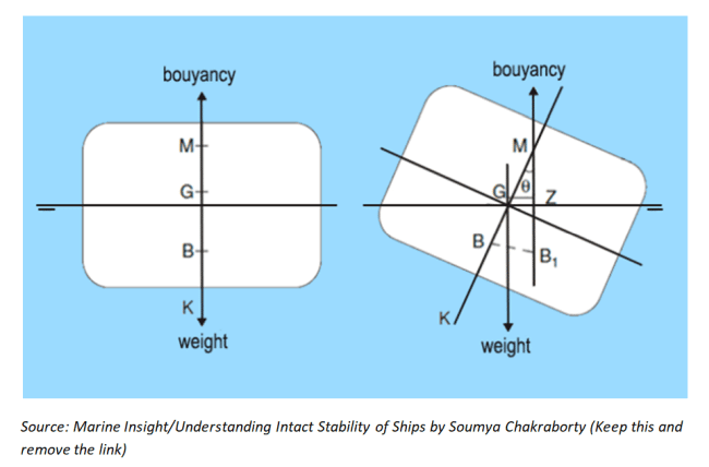
Refer to the following figure to understand that when a ship heels to any angle, a portion of the lower side of the ship is now submerged, and a portion of the hull from the upper side emerges out of the water. This can be noticed by visualizing the hull when the waterline was WL (without heel), and when the waterline was changed to W1L1 (after heel).
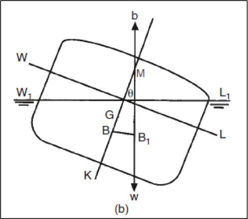
Due to this shift of submerged volume, there is a shift of the center of buoyancy from the centerline to the side that is lower after the heel. The new position of center of buoyancy is illustrated as B1. If a vertical line is extended from the new center of buoyancy, then the point at which this line meets the centerline of the ship, is called the transverse metacenter (shown as ‘M’) of the ship.
4. Center of Floatation (LCF):
When the ship floats at a particular draft, any trimming moment acting on the ship would act about a particular point on the water plane. This point is the centroid of the area of the water plane, and is called the center of the floatation. The distance of the center of floatation is read with respect to either of the perpendiculars or the mid-ship, and is abbreviated as LCF.
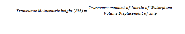
5. Metacentric Radius (BM):
The metacentric radius of a ship is the vertical distance between its center of buoyancy and metacenter (refer to figure 3 or 4). This parameter can be visualized as the length of the string of a swinging pendulum of the center of gravity of the pendulum coincides the center of buoyancy of the ship. In other words, the ship behaves as a pendulum swinging about its metacenter. It is a different fact that, the metacenter of the ship changes itself, every moment. Why? Because with every angle of heel, the transverse shift in center of buoyancy (as shown in Figure 4) will vary, therefore creating a new metacenter.
The importance of this parameter can be realised when the mathematical expression of metacentric radius is investigated.
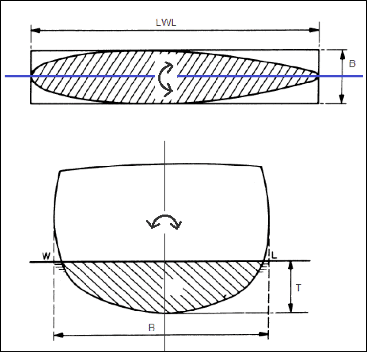
Now, what is the transverse moment of inertia of water plane? Refer to the figure below. A ship floating at a particular draft (T), has a unique water plane. When the ship rolls in the condition, if one looks from the top, the entire water plane area seems to oscillate about its longitudinal centroidal axis (shown in blue). The area moment of inertia of this waterplane area about its centroidal axis is the transverse moment of inertia of waterplane at the corresponding draft.
In the later part of this series, we will see the vital role this parameter plays in the stability of a surface ship, and how it also determines a lot of design decisions.
6. Metacentric Height (GM):
The vertical distance from the center of gravity to the metacenter is called the metacentric height. You will come across this term numerous times in this article, and a designer is probably most concerned about this parameter during the entire design process. IMO Codes of Stability for Ships have laid stability criteria for ships that are mostly based on this parameter. So, what is it that makes this parameter so vital? That is something we will discuss for the most part of the later part of this article, and the next few parts of this series.
The value of GM needs to be obtained at various stages, right from initial design stage, to hull design stage, during stability analysis of a newly designed hull, after the construction of a ship, and during operations at sea. The methods used in these stages are different from each other, because:
- At each stage, the purpose behind the evaluation of GM differs.
- The known parameters required to evaluate the GM also vary at each stage.
For now, given the fact that we know the parameters: BM, KB, and KG, let’s just appreciate the most basic formula used to evaluate the metacentric height of a ship: (refer to figure 3 for visual assistance)

7. Moment to Change Trim by 1 Centimeter (MCT):
For a particular draft, it is the longitudinal moment (about the LCF) required to bring about a trim of 1 centimeter. This parameter plays vital role especially when the crew on board requires to load cargo in any one hold or ballast, or de-ballast, and predict the resultant trim caused by the action. Since the expression of this parameter does not play any significant role in understanding the concepts of ship stability, we will skip it. But do remember that, MCT is a very important hydrostatic parameter required by stability analysis softwares and crew operations.
8. Tonnes per Centimeter Immersion (TPC):
For a particular draft the weight required to be added onto the ship so as to cause a parallel sinkage of 1 centimeter, is expressed as the TPC. This, similar to MCT, is used extensively by the crew to predict the new drafts after any operation that involves addition or removal of weights from the ship. Following is the expression used to evaluate the TPC of a ship at any given draft:
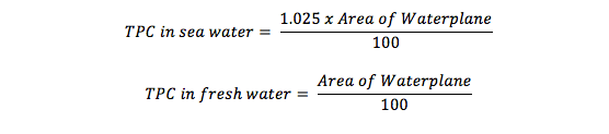
The above expressions give us some important results:
- TPC of a ship floating in water of uniform density, depends solely on the area of waterplane.
- The parallel sinkage resulting from a particular loading in fresh water would be more if the same loading was done in sea water.
- The crew must recalculate the predicted new drafts after loading or unloading when the ship moves from fresh water to sea or vice versa, to avoid unexpected observations.
Hydrostatic Curves:
All the hydrostatic parameters are calculated by a stability analysis software and plotted on a graph against different drafts. This graph is collectively called hydrostatic curves, and the same for a 200 passenger ship is shown below.
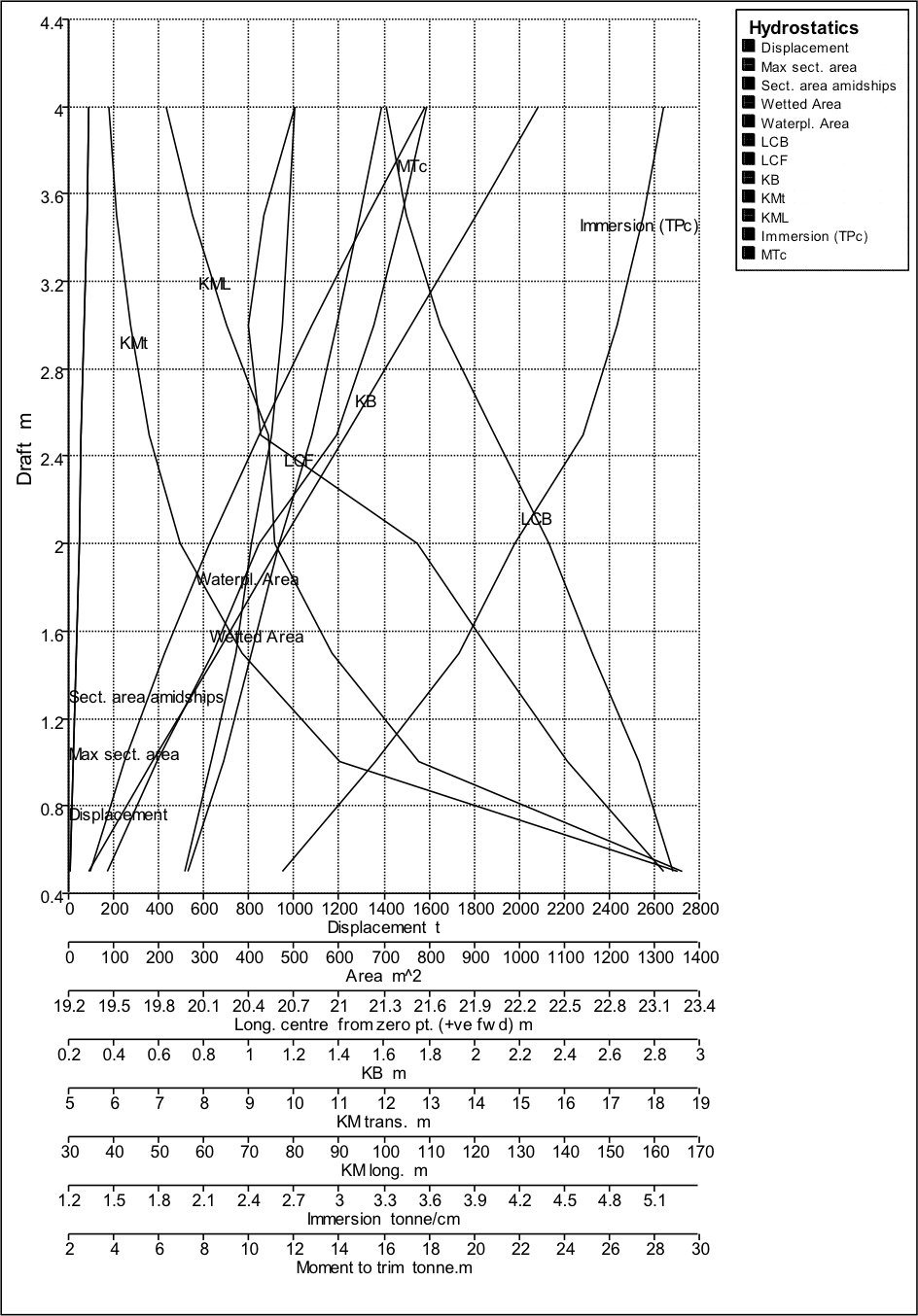
This graph is used by the crew on-board to instantly obtain the value of a hydrostatic parameter of the ship for a given draft. However, one needs to be careful about the multi-scale horizontal axis that is used here, since multiple parameters with different units are plotted on the same graph.
Some important observations can be made by studying the nature of hydrostatic curves, and they are discussed below:
- The only hydrostatic parameters that decrease with increase in draft are height of metacenter from the keel (KM), and longitudinal center of buoyancy (LCB). Remember, here, the LCB is calculated from the forward perpendicular (read horizontal axis in the graph), which means, a decreasing LCB with increasing draft implies, the LCB moves forward with increase in draft. But let us study this further. Does it hold true for all ships? While, the nature of KM is mostly the same, the nature of change of LCB with draft will vary according to the form of the hull. The above graph was for a passenger ship with a fine stern, as shown in the following figure.
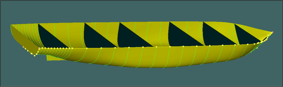
A fine stern means, with increase in draft, the percentage of submerged volume towards the forward of the midship increases more rapidly than the submerged volume in the aft. Hence, at larger drafts, a majority of the submerged volume will be concentrated towards the forward of the midship.
If this would have been a ship with finer bow and fuller stern, an increase in draft would have caused the LCB to shift towards the aft, thereby showing opposite nature on the hydrostatic curve. A ship designer can therefore predict the hullform of a ship just by looking at its LCB curve.
The MCT of all surface ships usually increase with increase in draft. Which means, a surface ship is very sensitive to trimming moments while floating in low draft conditions.
8. Curves of Form:
The various parameters of form (Block coefficient- CB, Prismatic Coefficient- CP, Water plane area coefficient- CWP, and Midship area coefficient CM) are also calculated and plotted in a graph against different drafts, as shown in the figure below.
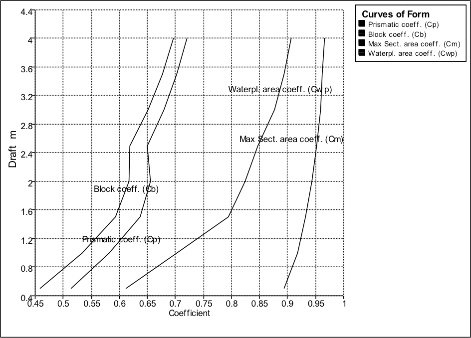
Though these parameters are not important for the crew, they play important role in optimizing the hull shape, and fairing the hull to a fine shape. If you notice the nature of the curves in the figure, the curves are not smooth. This implies that the hull at this stage of design, is not completely smooth, and would result in increased resistance. The same also applies to all the hydrostatic curves. Both these curves, along with the sectional area curve of a ship are simultaneously referred to, at each stage of hull modification, until a smooth set of curves are obtained.
This article has acquainted you with the hydrostatics of a surface ships, the understanding of which will play a vital role in studying the stability of ships. You can now recognize each hydrostatic parameter that appears further, its significance, and how it is represented on the stability book of a ship in form of curves.
The next article will discuss the basic concepts of ship stability which includes an introduction to intact stability and damaged stability, with detailed understanding of evaluation of intact stability of a ship along with various cases that affect the same.
Do you have info to share with us ? Suggest a correction


Latest Naval Arch Articles You Would Like:

Subscribe To Our Newsletters
By subscribing, you agree to our Privacy Policy and may receive occasional deal communications; you can unsubscribe anytime.
Fantastic. I’m passioned of nautical sciences. Thanks for share with us all the information about these topic.
very very interesting and very a very clear way to share your knowledge,is not very often that you get clear information on stability and hydrostatics in the way that you diid,congratulations
Soumya, Many thanks for this piece. Being in the marine engineering industry I have heard many dry and unnecessarily confusing discussions of this subject so it was a treat to read such a clearly laid out article.
Hai chakri
Its really interesting , the Topic which you shared. Have you shared any article about Catamaran, If not could you share your valuable Knowledge with us.
thankyou very much in advance.
@Mouolasaheb: You can check these articles:
https://www.marineinsight.com/tag/catamaran/
Thanks for sharing good for my knowledge to learn more on ships stability, for loading cargo operations on plywood’s. grains, wind mill tower, bulk cargo etc..
Hope can provide more info.
Thank you
In an effort to try and understand ship design and hydro-statics, I have read several poorly explained documents on-line and have gained only a smattering of knowledge and no more than scant understanding of the terminology and the forces at play on maritime vessels.
I then come across this series of articles by Soumya Chakraborty hoping to make more sense of my small degree of knowledge and to finally fulfill my search for an understanding of this subject.
Well, frankly I’m flabbergasted! This article is so full of sloppy presentation, woolly thinking and sheer inaccuracies that even with my minuscule knowledge I can recognise when the things being explained are clearly wrong.
Try these few excerpts:-
“2. Center of Buoyancy (CB):
The longitudinal position of the center of buoyancy with respect to any reference point on the ship is called the longitudinal center of gravity (LCB).
“5. Metacentric Radius (BM):
The metacentric height of a ship is the vertical distance between its center of buoyancy and metacentre”
“6. Metacentric Height (GM):
The vertical distance from the center of gravity to the metacenter is called the metacentric height.”
“4. Center of Floatation (LCF):
When the ship floats at a particular draft, any trimming moment acting on the ship would act about a particular point on the water plane. This point is the centroid of the area of the water plane, and is called the center of the floatation.”
So the ship rotates in pitch and roll around the CF, but then Soumya says
“5. Metacentric Radius (BM):
…In other words, the ship behaves as a pendulum swinging about its metacenter.”
At this point I gave up! I don’t feel confident that I can accept anything this man has to say as being correct!
I look at it this way, this is a serious subject with a lot of money and even lives dependent on the results. The least one can expect from one’s teachers is that they know what they’re talking about and have taken the time to get it right so that their students can have confidence in their teachings.
Unfortunately and with all due respect, I find Mr Soumya Chakraborty has failed in this task and I will not be wasting my time reading any more of his articles.
Dear Mr Ryder,
Thank you for reading my article and taking out the time to point out your concerns regarding the same. However, the logic behind your pointing out the so-called inaccuracies, as you say, seems questionable to me, because the information in the article is correct. I will substantiate with the following points:
LCB: While the point on which the buoyancy force acts is fixed in static conditions, the ‘value’ of the LCB varies depending on your reference point. While many designers prefer to consider the stern as the reference point, there are some who prefer the zeroth station as the reference. However, that does not change the underlying fundamentals. Having hoped you would have understood this point, please read the definition of LCB in my article now, and it should be clearer.
BM (Metacentric Radius): There has been a typing error in the definition, which should be corrected to metacentric ‘radius’. Thank you for pointing this out, I shall get it rectified. Having said that, the fact that the vertical distance between the center of buoyancy and the metacentre is the metacentric radius, remains unchanged.
GM (Metacentric Height): Since ages, the GM has been known to be the metacentric height of the ship. In the transverse axis, the distance vertical between the VCG and the Metacentre is the transverse GM, and the same theory extends to the longitudinal direction for the longitudinal GM. I don’t see why you would find this definition questionable.
LCF (Longitudinal Centre of Floatation): Any trimming moment acts “about” the LCF. In other words, when the trimming moment on the ship is calculated, the LCF is considered as the fulcrum. Do understand that the LCF is not a physical point on the ship’s hull, but a point of reference for static stability calculations. You could as well visualise it in this way- When you add weight to the ship at a point that lies exactly on the LCF, the trimming moment is zero. Having said that, let’s come to the next point.
The ship “behaves as a” pendulum swinging about its metacentre. There is a significant difference between a point about which a trimming moment is calculated and the point about which the ship “behaves as a” pendulum. This analogy only helps one to visualize the heeling and trimming of a ship, to draw the point that while heeling the CG of the ship forms an imaginary circle with the metacentre as its centre. Does that mean the imaginary circle remains the same? No. When we discuss static stability, we deal with instantaneous scenarios, more like snapshots of the dynamic scenarios. So when viewed dynamically, the metacentre of the ship actually changes with changing roll angle (Since the underwater volume would change, resulting in change in displacement, sometimes the metacentre changes due to shift in ballast within the ship, or due to shifting of cargo weight). In the longitudinal direction, the longitudinal metacentre would shift with trimming action due to asymmetric volumetric distribution in the forward and aft sections of the hull. So in dynamic conditions, the metacentre itself shifts with changing displacements. The pendulum analogy hence is only restricted to aid a reader in the visualisation of the instantaneous roll in case of static stability, where the roll angle is usually limited, beyond which, the theories and formulae of static stability do not hold true.
Bottom line, other than the typographical error, I do not see any incorrect information in this article as alleged by you. We, at Marine Insight, do not share incorrect information with our readers. I would also recommend you to read “Principles of Naval Architecture- Volume 1, by Edward V. Lewis”, published by SNAME, or “Basic Ship Theory- Vol.1 by Eric Tupper and K.J. Rawson”. The chapters on stability shall clear your concepts to and give you a deeper understanding. Ship stability is a vast subject in itself, and this article is a very introductory version of the terms related to ship stability. So as to appreciate the concepts and understand them from a wider point of view, one needs to indulge in further reading, during which, one is expected to come up with questions that at times challenge his/her previous understanding of the concept itself. Understanding ship stability is an iterative process. The only way to get better at it and appreciate the concepts is to solve problems related to the concepts, and get your doubts clarified whenever they come up. I hope I have been able to address your concerns.
Thank you,
Soumya.
THANK YOU FOR A GOOD CONTENT
Very informative. Keep it up dude