

Ship Stability: Damaged Stability of Ships
In all the previous articles of this series, we have discussed on various aspects of the intact stability of ships. In other words, whatever theories and cases of stability we have dealt with have, till now, considered that the hull of the ship is intact, and does not allow ingress of sea water into any compartment. Remember how we introduced the concept of stability in the first article of this series? That there are two major types of stability that concern surface ships- Intact Stability and Damaged Stability. This article will deal with the latter.
The study of damaged stability of a surface ship comes of use when the ship’s watertight hull is affected in a way that allows water to flood any compartment within the ship’s hull. Since this changes the stability parameters of the ship, the extent of which depends on the extent of damage and flooding, it is studied separately from intact stability.
Before going into the methods that are used to evaluate the damaged stability of a ship, we will discuss the effects of flooding on a ship:
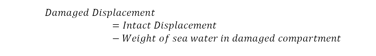
- Change of Draft: Flooding results in entry of water into the ship’s damaged compartment. This will cause a change in draft to the point where the displacement of the undamaged (intact) part of the ship will be equal to the displacement before damage less the weight of the water that entered the ship after flooding. To express it:
- Change of Trim: Ingress of water in a compartment can be considered as an addition of weight to any point along the length of the ship. This causes a change in the trim of the ship.
- Heeling: The ship will heel if the damaged compartment is unsymmetrically positioned about the centreline of the ship. If the metacentric height of the ship in the flooded condition is negative, the damaged ship is rendered unstable. In such a case, the ship would capsize if the flooded compartment is unsymmetrical about the centreline, and is prone to capsize by action of any external heeling moment if the compartment is symmetrical about the centreline.
- Change in Stability: The metacentric height of the ship changes due to flooding. This can be explained by the general expression of metacentric height:

The explanation of reduction in stability can be done in two ways, which is exactly what we will study in this article, but at a later stage. For now, it should suffice to understand that when a ship is flooded, it results in a change of KB and BM values. The KB rises due to flooding, and it may rise further due to change in the ship’s trim. However, there is a significant reduction in BM, which is a function of the area moment of the ship’s water plane. Why? We will look into that when we study the Lost Buoyancy Analysis.
- Change in Freeboard: The increase in draft of the flooded ship results in reduction of freeboard, which poses a great threat to the residual buoyancy of the ship. Even though the metacentric height may be positive after flooding, reduction in freeboard to a point where the deck is immersed, decreases the ship’s range of stability. This means that the ship could now capsize due to external forces of wind or waves.
- Loss of the ship: One of the most common terms that is used in damaged condition of a ship, is Margin Line. The Margin Line of a ship is an imaginary waterline considered 75 mm below the uppermost continuous watertight deck. If a ship is damaged, it is considered to be safe only if the margin line is not immersed. Once the waterline reaches the margin line at any point along the length of the ship, the ship is considered to be unsafe, and evacuation becomes mandatory.
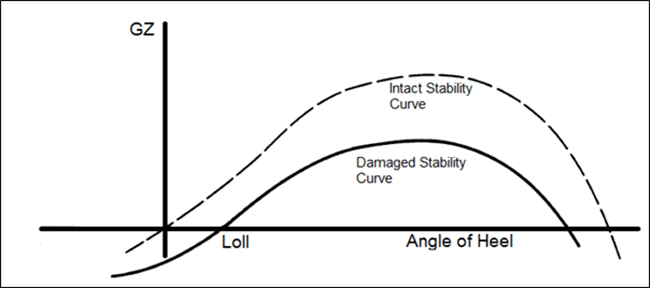
The reduction in metacentric height due to damage can be extrapolated to the stability curve as a reduction in height of the GZ curve and range of stability, as shown in the figure above. So if the loss in metacentric height is such that the remaining maximum righting lever (GZ) is less than the heeling moment, the ship will capsize. It is therefore, the designers work to:
- Design the subdivision in such a way that the remaining righting arm is sufficient upto a certain level of damage.
- To identify the extent of damage that can be considered safe for the ship.
Concept of Subdivision of a Ship:
Traditionally, a ship is divided longitudinally into a number of watertight compartments to restrict the flooding to one or more compartments in case of damage. This prevents progressive flooding (i.e. flooding across the entire ship’s length in case of a damage at any location). The compartmentalization is done by means of transverse watertight bulkheads. But the interesting question that arises here is, how many watertight bulkheads would a particular ship require? How many compartments do we divide a ship into? These are answers that need to be answered at a very initial phase of the design, most usually, in the concept design phase.
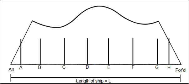
To understand the ‘how’s of this concept, we first need to understand the concept of “floodable” length. Refer to the figure underneath to follow the concept further.
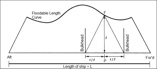
For any point ‘P’ along the length of the ship, the floodable length (l) is the maximum portion of the ship’s length with the point ‘P’ at the center that can be completely flooded symmetrically without immersing the margin line. For our convenience, we represent the floodable length of every point on the vertical axis. So, for the point ‘P’ we can plot the floodable length at point ‘F’ on the vertical axis. Similarly, when the floodable lengths of all the points on the ship are plotted, we obtain the Floodable Length Curve.
So, what is the use of Floodable Length Curves? The advantage that these curves come with is that they can be plotted very inexpensively, and at a very initial stage of the design. This makes it possible for the designers to decide on the number of watertight compartments, marginal compartments, and transverse bulkheads required by the ship.
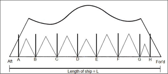
We will first see, how the position of bulkheads are fixed, based on the floodable length curves. Follow the above figure again. Suppose we place two watertight bulkheads at a distance of ‘l’ and as ‘P’ as their midpoint. We know, that since the floodable length at ‘P’ is ‘l’, by the definition of floodable length, if the compartment of length ‘l’ and with ‘P’ as its mid-point is flooded, the margin line will remain above the waterline. Hence, the compartment between the bulkheads shown in the above figure is a safe design.
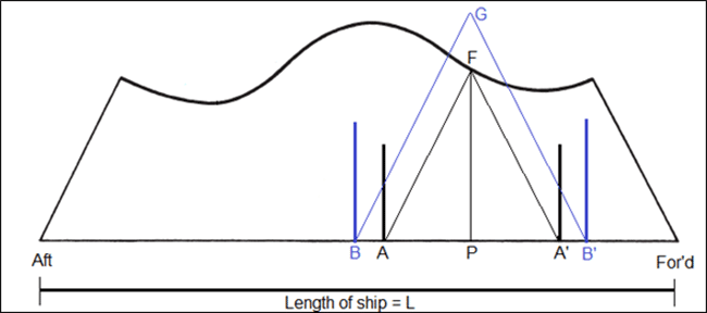
Note that in the above figure, the height of the triangle drawn from the two bulkhead is equal to the floodable length of the point ‘P’. In other words, to ensure if a compartment is safe or not, we simply need to draw a triangle from the two bulkheads. The height of the triangle should be equal to the length of the compartment. If the vertex of the triangle meets the floodable length curve, or is below the curve, the compartment is safe (as shown for compartment AA’ in the figure below). However, if we now increase the length of the compartment from AA’ to BB’ (as shown in blue), the vertex of the triangle exceeds the floodable length curve. In other words, the bulkheads, if placed at BB’, would result in submergence of the margin line if the compartment between the bulkheads was to be completely flooded.
So, to check whether a particular compartment plan (a longitudinal distribution of watertight bulkheads along the ship’s length) is safe, designers follow the steps as explained below:
Step 1: The floodable length curve is plotted.
Step 2: Watertight bulkheads are placed at random, but known positions along the length of the ship, thus dividing it into a number of watertight compartments.
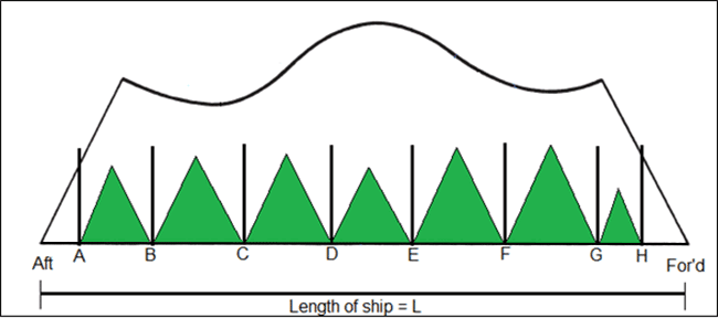
Step 3: Triangles are drawn for each compartment such that the height of each triangle is equal to the length of the compartment.
Step 4: At this stage, it is important for the designer to know what compartment standard the ship has to be designed to. So what is a Compartment Standard? A ship is said to have a Single Compartment Standard if it is designed to be sea-worthy (should be able to remain afloat, and margin line should not be immersed) even after any one of its watertight compartments have been damaged completely. Similarly, a ship with Two Compartment Standard can remain afloat even after complete damage to any of its two adjacent watertight compartments.
So, once the compartment standard is fixed, the designer must now check the same using the obtained floodable length curve. For the compartment layout set in the above example, we have all the triangles with vertices below the floodable length curve (refer to the figure below). This means that the chosen compartment plan can be used to certify the ship with Single Compartment Standard.
But if the design of the ship demands a two compartment standard, the above check is not sufficient. In order to perform a two compartment standard check, the triangles need to be drawn in a way considering that two adjacent watertight compartments are damaged. For example, in the diagram below, the triangle AKC has been drawn for the case when compartments AB and BC are completely flooded. In simpler terms, we will now consider two adjacent compartments as one. The results obtained for the above case, is as shown below.
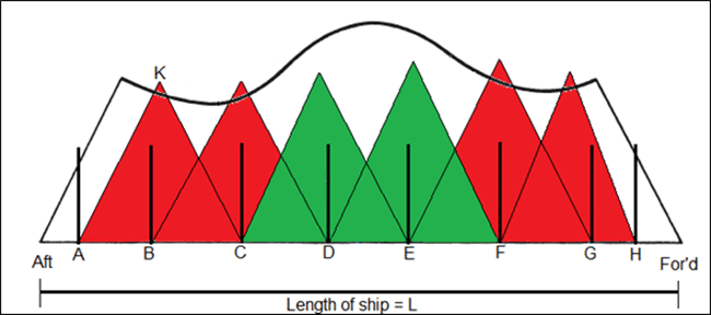
The results clearly tell us that the margin line would submerge if the following compartments were flooded together:
- Both AB and BC.
- Both BC and CD.
- Both EF and FG.
- Both FG and GH.
But the margin line would remain above the waterline for simultaneous flooding of either of the two cases:
- Both CD and DE.
- Both DE and EF.
In such a case, the ship is given a two compartment standard, but only for simultaneous flooding of compartments CD and EF or DE and EF. Hence, if in case of a damage to the engine room (which would usually be located in compartment BC), progressive flooding to the steering gear compartment (AB) or the compartment just forward of the engine room (CD) cannot be afforded to keep the margin line from submerging.
Concept of Permeability:
Practically, all the compartments in ships would contain items within them that would reduce the total volume that can be occupied by the flooded water. The items include stiffeners, web frames, longitudinals, brackets, beam knees, equipment, piping, and outfits. Hence, the ratio of the floodable volume to the total volume of the compartment gives the permeability of the compartment. It is denoted by µ, and is usually expressed in percentage.
The general values of permeability used for different types of compartments are listed below, followed by a logical understanding of the variation in the values:
Watertight Compartment – 95 to 97%
Accommodation spaces – 95%
Machinery compartments – 85%
Cargo holds – 60%
Stores – 60 %
What is to be observed here is that the permeability of machinery spaces (engine room, auxiliary machinery room, pump room, etc.) is lower than watertight compartments (like tanks, cofferdams, etc.) and accommodation spaces. The least permeability is obtained in cargo holds and stores which are usually stacked full or partially full, leaving lesser volume for flooded water.
The floodable length of each point along the ship’s length is multiplied by the permeability to obtain the Permissible Length. It is based on this permissible length curve, and not on the floodable length that we judge the final compartment standards of the ship. This is exactly what has been illustrated below, where the permissible length curves are first plotted for each permeability value.
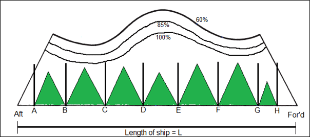
The permissible length curves for 85 percent and 60 percent permeability are now incorporated into the floodable subdivision diagram. Here, for machinery compartments (e.g. engine room compartment BC) the vertices for the triangle needs to be checked against the 85% curve, instead of the floodable length (100%) curve, which we did when permeability was not introduced. In this case, all compartments satisfy for single compartment standard.
The application of permeability would come to be noticed in a case illustrated below:
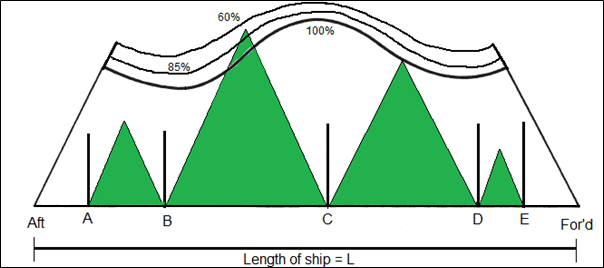
Here, the machinery compartment (AB) seems to be within the permissible length. But how do we assess whether compartment BC is safe or not? This is the subdivision diagram for a typical merchant ship. The compartment BC is generally used for cargo holds, where the permeability is as low as 60 percent. Hence, the triangle for this compartment is to be checked against the 60 percent permissible length curve, which determines that one compartment standard is achievable.
Another important concept that comes to play here, is that of Marginal Compartment. If you notice compartment CD, its length is exactly equal to the floodable length, which is why the vertex of its triangle coincides the floodable length curve. Such a compartment is called a Marginal Compartment. However, in this case, the marginal compartment does not behave as one because of the permeability factor. The compartment CD in merchant ships is usually used for cargo hold or forward stores, giving it a permeability of 60 percent.
It is therefore evident that though the triangles may overshoot the floodable length curve, the final analysis is to be made only after calculating the permeability of every compartment.
Evaluation of Damaged Stability Equilibrium Conditions:
The most important step in analysis of a damaged condition, is to calculate the equilibrium conditions, which include the final trim, heel and drafts after the location and extent of damage is known. There are two methods that are used for this purpose. We will only graze through the concepts of each,
- Lost Buoyancy Method: This method assumes that the damaged compartment does not contribute to the total buoyancy of the ship. Hence, the ship loses a part of its total waterplane, and its buoyancy, therefore reducing stability. This method is easier to use, because it is not iterative. On the other hand, the results obtained from this method are slightly less accurate than the other method.
- Added Weight Method: The added weight method considers the flooded water to be a weight added to a certain point in the ship. The problem is them solved like a traditional weight addition case, and the trim and drafts are calculated over a set of iterations. Though this process is time consuming, it provides more accurate results, and is hence used by most stability analysis software.
We have restricted our study to the conceptual understanding of subdivision and the two methods of evaluation have been discussed on a very primary level because they are very numerical in nature, and is hence out of the scope of our article. Detailed examples of both the methods can be found in published textbooks. What’s important to understand, is the conceptual application of damaged stability. These concepts are now applied in advanced levels to develop newer ways of understanding damaged stability of ships, something that has taken a probabilistic approach in the recent days.
Disclaimer: The authors’ views expressed in this article do not necessarily reflect the views of Marine Insight. Data and charts, if used, in the article have been sourced from available information and have not been authenticated by any statutory authority. The author and Marine Insight do not claim it to be accurate nor accept any responsibility for the same. The views constitute only the opinions and do not constitute any guidelines or recommendation on any course of action to be followed by the reader.
The article or images cannot be reproduced, copied, shared or used in any form without the permission of the author and Marine Insight.
Do you have info to share with us ? Suggest a correction


Latest Naval Arch Articles You Would Like:

Subscribe To Our Newsletters
By subscribing, you agree to our Privacy Policy and may receive occasional deal communications; you can unsubscribe anytime.
Very informative.
Am inspired!
There is one statement written in the article that “The floodable length of each point along the ship’s length is multiplied by the permeability to obtain the Permissible Length.” that I think its needed to be corrected as permissible length is a function of permeability and floodable length, as if its direct product then permissible length should be less when permeability is less but that’s not the case
The use of permeability is linked to cargo state of the ship. A ship can be two-compartment certificated when full loaded, but only one-compartment when in ballast because the different permeabilities.
The added weight method is not necessarily more accurate than lost buoyancy method. In fact, lost buoyancy method is closer to actual physics.
The article is extremely useful and its massively informative. Albeit, I personally think it would rather have been better if you had explained certain key terms like ‘draft’, ‘trim’ etc.
THANK YOU….
@Dan: Thank you for your input. We will pass on your comment and suggestion to our editors.