

Methods For Designing Ship’s Hull – A General Overview
The design of a ship hull is based on the specific geometric definition of a hull which influences the hydrostatics, general arrangement, strength and aesthetics of the vessel.
A naval architect has to apply his combined knowledge of designing and draftsmanship to arrive at the optimum hull form. An important aspect of preliminary design is to create a set of faired ship lines.
At this initial stage of design, the naval architect has to develop a set of ship lines of sufficient accuracy to be used for later design calculations from relatively sparse information. The resulting lines plan must not violate any of the implicit, and sometimes intuitive rules of hull form design with respect to fairness and practicability.
Mathematical methods for ship form design, especially when supported by computer systems with interactive graphics capabilities and skilfully applied by experienced designers, have become competitive to conventional graphical techniques with respect to time and cost.
In a ship design office the standard design for the development of ship lines can be done from one among the following ways:
- Geometrical hull form parameters.
- Single parent design.
- Multiple parent design.
The method of design used in the above three cases are referred as:
- Form parameter approach.
- Line distortion approach.
- Standard series approach.
Form Parameter Approach
As the name suggest this methods creates lines from the specific values of the parameters that define the significant curves of the hull form unlike the line distortion or standard series which require a parent design. Initially, the naval architect has to decide the type of fore and aft body so that the profile outline can be drawn. After determining the profile outline, a series of curves has to be drawn in order to design the initial hull form. These curves include the sectional area curve, design waterline curve etc. Each basic curve have been developed from its own form parameter input.
To start with the preliminary sectional area curve, one has to determine the midship sectional area first. This is done by choosing a suitable midship area coefficient.
Next step is to determine the suitable Longitudinal Center of Buoyancy (LCB) position from the hydrodynamic point of view. Sectional area can also be obtained by drawing a trapezium and smoothing it to give the desired shape.
In a similar manner, a half breadth plan of the Load Waterline Length (LWL) can be drawn to satisfy Area of water line and longitudinal centre of flotation (LCF) requirement. Also, the designer should keep in mind the fact that the length of run and entrance on LWL are less than the length of run and entrance on the Sectional Area Curve.
Another important characteristics of the LWL is the half angle of entrance which is a function of prismatic coefficient for many hull forms. Other basic curves include the deck outline, the main consideration being the deck area and the type of flare above LWL.
The final step would be to integrate the basic design curves by satisfying all the conditions of areas and LWL requirements, this is accompanied by an iterative process and surface fairing is done to generate the three dimensional hull surface.
Line Distortion Approach
It is one of the most common methods adopted in design offices to derive a set of lines plan. This is done by making some minor changes to the form parameters of the parent ship design. The lines distortion approach aims at arriving at a new lines plan by moderate extrapolation from the parent design by suitable mathematical operations.
For the transformation of a basic ship form to a desired ship form two methods of computation is used.
In the first method, the fore and the aft part of the ship were taken and transformed to get the design to their desired block coefficients and the second method, the correct block co-efficient and the longitudinal position of the center of buoyancy of the whole ship are used for the desired transformation. The first method is especially useful, if only the form of the fore body or the form of the after body is to be changed.
Line distortion method is fairly successful in dealing with moderate changes in limited number of form parameters. However it is limited to certain number of reasonable shapes and degenerate when pushed to extreme changes. To change one form parameter independently serves no useful purpose beyond a reasonable limit. Other form parameters have also to be varied in a coordinated way. The distortion method itself does not provide such co-ordination. When applied by a skilful designer it has the potential of achieving rather complex changes.
Standard Series Approach
It is similar to the line distortion approach but differs in deriving it’s parameters from not one but multiple parent designs. This requires a rich knowledge of the systematic hull form series. This method is useful for the generation of series of hull forms for resistance and propulsion tests. The interpolation method within this body of information is generally linear, but higher order curves can also be used. The range of variation in the series is however limited, which means that the forms that can be deduced from the series are also limited and only modest extrapolation is possible.
Basically, the designer has limited possibilities and his outcome design will have more dependent variables than independent variables. The standard series encompasses only some of the simpler variations in the hull like fullness and location of Longitudinal Centre of Buoyancy.
The main advantage of this standard series approach lies in its simplicity. In many feasibility studies of the early design stage it is sufficient to have a rough preliminary lines design that approximates the principal form characteristics desired. Such a design may serve as a dummy for several design calculations until a more elaborate lines plan is produced.
Watch: How Hull Resistance Affect Ship Speed-
Lines Development
The following steps are involved in the lines development process –
- Draw boundary lines which include elevation and plan of the keel, stem, stern, deck and chine lines if any.
- Drawing of sectional area curve as per requirement. This step may not be necessary while drawing planning boats and other small crafts.
- Drawing load water lines satisfying all requirement. Again, this may not be necessary for ships with chine form.
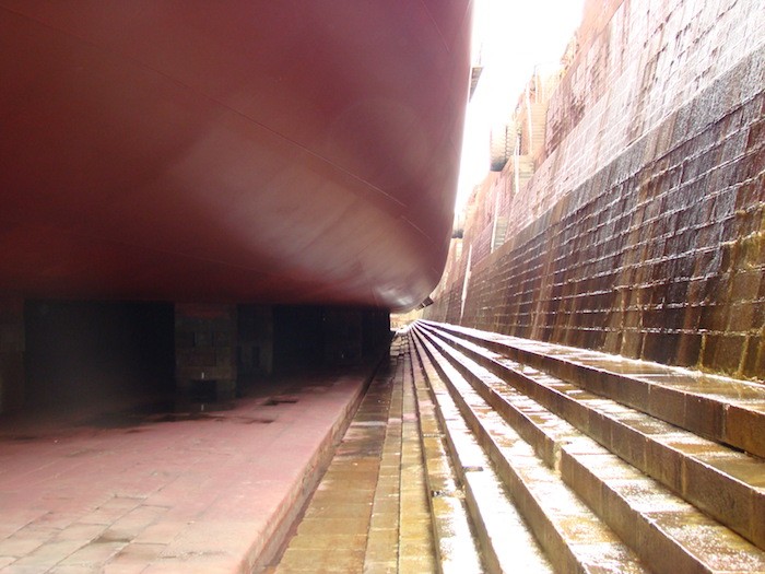
Stern Forms
During the design process of the stern section of the hull the following points should be considered –
- Low resistance should be ensured by avoiding rough surfaces like weld marks or ensuring no sudden change in the surface.
- Avoid any kind of vibration.
- High Propulsive efficiency this ensures uniform flow of water around the hull and good hull efficiency coefficient.
- The choice of the shape of the top side stern section should be decided on the basis of Froude number –
- The reduction in power for transom stern compared with cruiser stern increases with the Froude number.
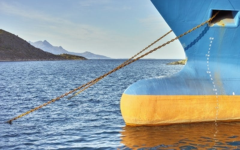
Forward Section Shape
There are basically two forward section shapes i.e, the V – shape or the U – shape. Each shape has its own advantages and disadvantages, let us look into a few of them individually.
Advantages of V sections
- Better sea keeping abilities in terms of reserve buoyancy and reduced slamming effects.
- Small wetted surface and lower steel weight.
- Greater local breadth of the design waterline: associated with this is a greater moment of inertia of the waterplane and a higher center of buoyancy. Both effects increase the value of KM.
- Less curved surface, hence, ease of production.
- In ballast condition of a given displacement, the wedge form provides a greater draught and hence a decrease in block co-efficient. At a smaller draught the decreased block co-efficient leads to lower resistance than in the case with equivalent U-form. Also less ballast is needed to achieve the desired immersion.
Advantages of U sections
- V sections in the fore-body have a higher wave-making resistance with lower frictional resistance. This leads to higher overall resistance than U sections in a particular range of Froude numbers from 0.18 to 0.25.
The presence of computer aided ship form generation software has made the process of designing much simpler and smoother compared to what was done a few decades ago.
The basic concepts still remains the same .i.e, determining the basic form parameters and generating the rest of the rest of the lines plan from it. However, the computer merely helps the designer as a guide and also as a slave doing the required calculations, but does not replace him.
Over to you…
Do you know any important method to design ship’s hull?
Let’s know in the comments below.
Do you have info to share with us ? Suggest a correction


Latest Naval Arch Articles You Would Like:

Subscribe To Our Newsletters
By subscribing, you agree to our Privacy Policy and may receive occasional deal communications; you can unsubscribe anytime.
I draw a shell of PCC under my 14th years on command of this type of vessel. I use rhinoceros. Used a free approch for it. Developed Anti Pitch bulb e try To have a reduction of consumption with news idea. Of course i must try this ideas under model test.
A. Rocca – Master
More valuble details. Highly apprecitae
It seems to me the energy wasted is creating bow wave.
this could be avoided by having an open bow ,socking the water
through the middle of the ship and expelling through the stern
for propulsion
there would be many variations of this but the principal is the same
example a swimmer is clawing the water from the front
and pushing it behind………..Albert Miller