

Dry Docking of Ships – Understanding Stability And Docking Plan
The process of docking and undocking of ships might not seem like an important operation. However, it’s a process that is carried out more than once, not only by shipbuilding yards during the construction of a ship, but also as regular part of the ship’s lifetime. The understanding of the process of docking is specialised, and hence, not many naval architects or engineers are thorough with the inner details of docking. Professionals who are specialised in carrying out docking and undocking of ships are commonly known as Dock Masters.
But why is it important for ship designers to know about the docking processes? It is because, the process of docking is done by the aid of a series of drawings and plans, which are prepared by designers, based on certain calculations. Hence, knowing docking processes, docking calculations, and understanding how to read docking plans is an important skill for designers working in shipyards.
From time to time, it becomes important to carry out repairs in the underwater portion of the hull. Such repairs may include renewal of the sacrificial anodes, refit of the propellers, overhauling of the propulsion shafts, repair of rudders, underwater hull blasting to remove fouling, etc. In order to carry out these repairs, the underwater portion of the hull needs to be made accessible, which is the purpose served by a dry dock. It has also become a common practice in large shipyards to build their ships on dry docks, and float it out when ready for trials. For such procedures, the docking plans need to be prepared taking into consideration the increase in weight of the ship structure along the building time. Once the ship has been built, the dry dock is flooded and the ship is undocked. The calculations for undocking also play a major role in the process because it is during undocking that the the ship is at a risk of capsizing.
Stability during Docking:
When the ship enters a dry dock, it must have a positive metacentric height; and is usually trimmed by stern. The floor of the dry dock is lined with keel blocks, which are so arranged such that they can bear the weight of the ship. When the ship enters the dry dock, her centerline is first brought in line with the centerline of the keel blocks by using a combination of plum lines and Leica theodolite.
The dock gates are then closed and the water is pumped out of the dock in stages. Since the ship has a trim by stern, the stern of the ship will first sit on the keel blocks. The rate of pumping out water is reduced as the stern is almost about to touch the keel blocks. The reason is, it is from this stage of the docking procedure when the stability of the ship starts getting critical. The interval of time from when the stern takes the blocks to the moment when the entire ship’s weight is borne by the blocks is called Critical Period. We will understand the details a little later.
When the stern of the ship takes the blocks, it is fixed to the shores (sides of the dock). This is carried out from aft to forward so that by the time the entire ship takes the blocks, it is fixed to the shores. When the ship is completely borne by the blocks, water is pumped out quickly from the dock.
So what happens during the critical period and why?
When the ship’s stern just touches the keel blocks, part of the ship’s weight is being borne by the keel blocks. The contact between the stern and the keel block creates a normal reaction or upthrust. The magnitude of this upward normal reaction increases as the water level in the dry dock reduces. It is this upthrust that creates a virtual reduction in the metacentric height of the ship. Hence it is very crucial to maintain sufficient positive metacentric height before docking, lacking which, the ship may heel over to either side, or even slip off the keel blocks and capsize.

The purpose, hence, is to calculate the metacentric height of the ship at different stages of the docking process, and ensure that it does not fall below the safe limit. Follow the figure underneath, which shows a ship that has just touched the keel block by its stern. The location of the center of floatation (F) is known from the hydrostatic curves at the given displacement. Since the location of the stern is a known point, its distance from the center of floatation (l) can be calculated instantly.
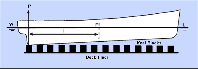
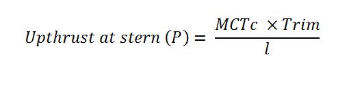
The moment to change trim by 1 cm (MCTc) is a hydrostatic parameter that is obtained from the hydrostatic curves. So, for a known value of trim, the following equation is obtained:
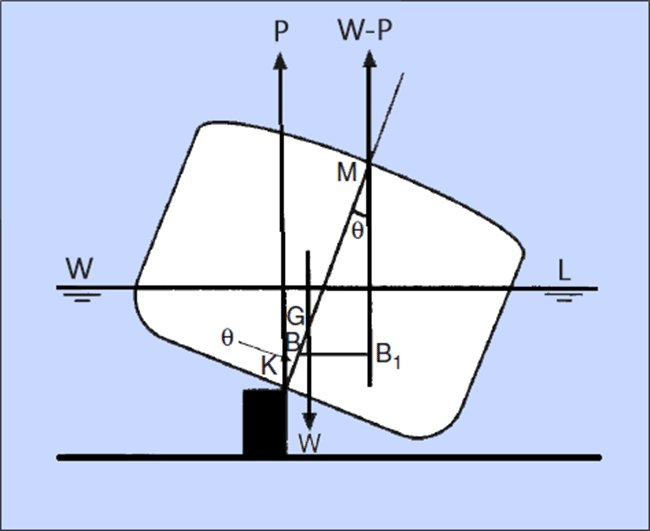
The above figure shows the transverse view of a ship in the critical period, which has been inclined by an external force to an angle theta (Ɵ). The weight of the ship (W) acts vertically down through the center of gravity (G). The upward reaction force (P) acts vertically upwards through the keel of the ship. This is a normal reaction force, and is equal to the portion of the weight of the ship being borne by the keel blocks. For equilibrium, the remaining portion of the weight of the ship (W-P) will be supported by the buoyancy, which will act through the initial metacentric height of the ship (M).
What we have now, are three vertical parallel forces acting on the ship:
- Weight (W) acting downward.
- Keel block upthrust (P) acting upward.
- Buoyancy (W-P) acting upward.
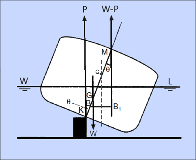
The upthrust force (P) can be considered to have an effect similar to that of removal of a weight from the ship. This has the virtual effect of rising the center of gravity of the ship from the point ‘G’ to ‘G1’. The metacentric height therefore reduces from GM to G1M, as shown in the diagram below:
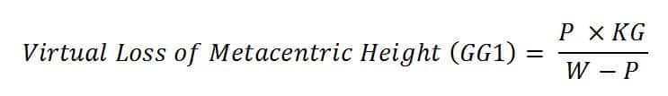
The virtual reduction in metacentric height at any stage of the docking process can be calculated by the following expression:
This calculation must be carried out for the condition when the ship has just touched the keel blocks throughout its length. It is at this point that the keel block upthrust is maximum, and the risk of tipping over or slipping from keel blocks is most likely if the metacentric height is too low or negative.

Docking Plans:
A docking plan is a document that is prepared for every ship during its preliminary design phase. All the information required to bring a ship to a dry dock are included in its docking plan. While most of the information is condensed into drawings, one must also refer to the textual references and notes provided, because they also inform us about the type of dry dock that is being used, and technical specifications of dry dock that should be met before the ship is docked.
The contents of a typical docking plan are discussed below:
- Table of Hydrostatics and Hydrostatic Curves:
The first few hydrostatics that must be checked before a ship enters a dry dock are:
- Forward draft.
- Aft draft.
- Longitudinal Center of Buoyancy.
- Moment to Change Trim by 1cm.
- Center of Gravity.
- Longitudinal Center of Floatation.
- Transverse metacenter.
Since it is not preferred to provide the information in an easily obtainable manner, a tabular form of hydrostatic data is more preferable than the curves. In case of intermediate values, interpolation methods are used, and then tallied with the curves.
- Docking Drawing – Elevation View:
The elevation view of the docking drawing gives the following information:
- Location of the Longitudinal Reference Point (LRP), i.e. the point from which all the longitudinal dimensions are measured.
- Location of Aft Perpendicular and Forward Perpendicular.
- Location of the end of skeg.
- Frame spacing.
- Longitudinal clearance required for removal of shaft.
- Longitudinal clearance required for removal of rudder.
- Location of draft marks along the ship.
- Location of the first and last keel blocks.
- Docking Drawing – Plan View:
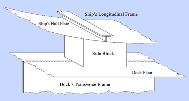
The plan view would show the location of the keel blocks along the centerline of the ship. Most large ships with wide beam are also placed on a series of side blocks, and the layout of the same is laid out in the plan view. The position of every hull opening and hull protrusions (both, above and below the waterline) are also marked in this drawing, in order to make sure they do not interfere with the dock blocks.
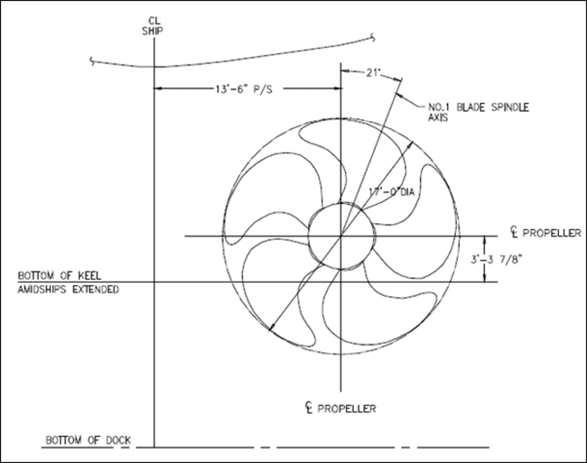
- Cross Section at Propellers:
Sufficient clearance should be ensured between the propeller tip and the dock floor. There should also be adequate longitudinal and transverse clearances for enabling removal of the propeller. It is due to this reason, the cross sectional view of the propeller (usually looking forward) is provided in the dock plans. The centerline of the ship, centerline of the propeller disc, distance between the ship’s centerline and the propeller centerline, and keel line of the amidship is also shown in the same diagram, as illustrated below.
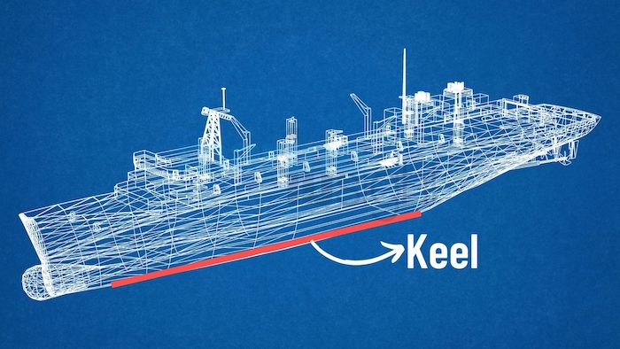
- Keel Profile:
The keel profile shows the elevation of the keel line along the ship’s length. This profile is used to determine the height of the keel blocks at each longitudinal position, taking into consideration the load distribution curve of the ship.
- Bilge Keel Clearances:
The bilge keel extends as an appendage from the sides of the hull. The distance from the bilge keel to the ship’s centerline must be specified in the docking plan. The height of the bilge keel from the ship’s keel is used to ensure there is sufficient vertical clearance available during docking and undocking.
Load Distribution and Block Pressure:
Since the keel blocks bear the weight of the ship, the load distribution curve for the keel blocks is derived from the weight curve of the ship, which is comprised of a combination of distributed and concentrated weights. The weight of the hull girder and superstructure are distributed along the ship’s length. But weights like that of machinery, equipment, transverse bulkheads, fuel oil, fresh water are considered as concentrated weights.
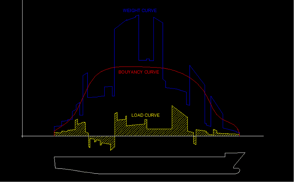
The figure above shows the nature of the weight curve for a ship (shown in blue). In case of dry docking, the buoyancy curve becomes non-existent. However, there is an important change that is made in the weight curve. If you notice carefully, when a ship is afloat, it is supported by buoyancy throughout its length. But a ship on a dry dock is not supported by keel blocks throughout its length. This is because of the shape of the ship’s hull. Notice in the figure below, that a significant length of the ship forward and aft are not supported by the keel blocks directly, due to the overhangs at the bow and stern.
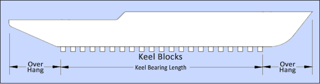
Though the weight of the overhang regions is not directly exerted on the keel blocks, the total weight of the ship is supported by the total area of the keel blocks. To compensate for this effect, the weight curve of the ship is accordingly changed so as to transfer the weights of the overhang regions onto the region supported by the blocks (also called keel bearing length).
The maximum pressure that can be exerted on the blocks is a function of the material used for the blocks. This value being a constant, the minimum block area required for each block is calculated. If you observe the nature of the weight curve, it is usually high at the mid ship region and decreases at the forward and aft. It is due to this reason that the weight bearing area of the keel blocks increase as we move towards the mid ship. The pressure exerted on the keel blocks is called the block pressure, and the Average Block Pressure is the total weight of the ship divided by the total bearing area.
Now, docking plans are created for every ship taking into consideration the dry dock where it is likely to be dry docked during most of its major repair and refits. But there may arise situations where a vessel is to be dry docked at a different dock, where the docking plan is to be modified to suit the dry dock. There are a number of conditions that must be met in order to prevent any structural failure in such cases:
- The number of blocks may be different from the original docking plan, but the total bearing area must be sufficient to maintain the block pressure below the material safe limits. This ensures that the hull does not have excessive loads that could cause damage to itself.
- The floor of the dock has its own strength limits, which depends on the material of the dock floor. This makes the load on the dock floor per unit length a limiting parameter too. Now, if any block is removed or repositioned from the original plan, the load on the dock floor per unit length must be recalculated and checked for the given factor of safety.
- The dock floor is strengthened underneath by transverse frames that run along the breadth of the dock. When keel blocks or side blocks are repositioned from the original dock plan, it should be ensured that the new position of the block is such that it comes under a strength bearing member of the ship (bulkhead, longitudinal girder, etc.) and also sits on top of a dock floor transverse. This is to ensure that there is a proper stress flow from the ship’s hull to the keel blocks, and finally to the dock floor.
- It must be checked that the new positions of the keel blocks do not interfere with any underwater opening or protrusion. The heights of the new blocks should be calculated by interpolating the values of the two closest values from the original docking plan.
It is evident from the article, that the calculations and analyses that go into creating docking plans and executing the process require equal attention from aspects of stability, as well as the strength of the ship. Most of the failures in dry docking or undocking of ships have been due to
- Improper evaluation of loading of the ship.
- Improper loading of the ship during docking (concentrated weights like fuel oil, lube oil, fresh water, ballast water, etc. should not be stored in overhang regions during dry docking).
- Improper stability assessment of the ship during the critical period.
While these are the primary reasons, there are a series of many which can only be discussed in detail in courses that are designed specifically for dock masters. Today, dock masters use software to pre-determine the docking plans of ships, and the results are then tallied with the existing docking plan. Even then, this procedure remains one of the most crucial ones in the ship-building and ship repair industries, owing to its demand for extremely low margin for error.
Further Reading:
Disclaimer: The authors’ views expressed in this article do not necessarily reflect the views of Marine Insight. Data and charts, if used, in the article have been sourced from available information and have not been authenticated by any statutory authority. The author and Marine Insight do not claim it to be accurate nor accept any responsibility for the same. The views constitute only the opinions and do not constitute any guidelines or recommendation on any course of action to be followed by the reader.
The article or images cannot be reproduced, copied, shared or used in any form without the permission of the author and Marine Insight.
Do you have info to share with us ? Suggest a correction


Latest Naval Arch Articles You Would Like:


Subscribe To Our Newsletters
By subscribing, you agree to our Privacy Policy and may receive occasional deal communications; you can unsubscribe anytime.
ITS VERY FANTASTIC
it was very easy to understand….thx for such a great blog
Glad it is useful to fellow seafarers.
1-why ship enters in dock with trim by stern .
2- how to paint the area between keel blocks and keel.
@Ashok: Use our forums to ask your exam related queries: https://forums.marineinsight.com
It is a great blog ,THKS!
Is there any rule or instruction for ship docking and undocking?
@Jason; Thank you for your kind words.
The docking/ undocking procedure will vary on size and type of the ship. There may be local regulations / yard requirements which you need to follow. There are no broader rules for docking /undocking.
@ Anish; thanks for your reply, is there any local regulations / yard requirements for ship docking/undocking available in your hand? will you pls sent to me if you can do me a favor?
email box: wangxiaohua@cmhk.com
Amazing article and was very interesting to read. Engineering is an amazing field. Thabks for the article and the level of detail.
@Srini: Thank you. Glad you enjoyed reading it.
Hi Anish, Informative and In simple words. Well Done. Thanks.
Thanks so much for the rightful information on dry docking,very explanatry.
@Gbadamosi: Glad the information is helpful. ????????
I just wanted to know how block area is painted which supports the vessel?
Also what is Drydock Version 1 & 2?
Hi Anish, well explained. Pls show the reverse act during un-docking when ship begins to float & recreation of COB upward
@A.Trivedi: Well noted your suggestion. I will definitely pass the topic to my editorial team. Thank you. ????????
This has covered almost everything one will need to know. Thanks for the article.
Will you please prepare another article on UN DOCKING OF A SHIP?
All the best
@Heri:
Thank you for the suggestion –
Sure. Meanwhile, please check this article – https://www.marineinsight.com/guidelines/checks-to-perform-on-ship-before-coming-out-of-the-dry-dock/
Hi. Very nicely brief one more question is that if tanker Is in loaded and had to proceed dry dock with cargo onboard what precautions we have to take kindly inform
Hi
How is the weight coming on each keel block determined. Is it measured using load cells or by other means?