

5 Stages Of Marine Machinery Installation On Ships
There is a misconception that the machinery installation onboard ships are all about lifting and mounting onto the foundation and tightening the bolt and nuts. Just to clarify, it is not as simple as that.
A wrong machinery installation can lead to severe vibrations, which can significantly affect the vessel performance. There are cases where machinery vibrations have caused severe structural damage. There are also cases wherein shaft misalignment has resulted in catastrophic failures of equipment.
In this article we will see five stages of Marine machinery installation as listed below:
1) Equipment lifting
2) Equipment positioning on to the Foundation
3) Equipment shaft alignment (in case of rotating machines)
4) Installation of pipelines
5) Commissioning

1. EQUIPMENT LIFTING
The lifting equipment for machinery on ships which includes cranes, lifting gears, spreader beams, shackles, and pad eyes should be of capacity at least 1.25 times the weight of the equipment lifting. Below points also needs to be noted:
- Prior to lifting conduct risk assessment
- Prepare a lifting plan and ensure the lifting plan is communicated to the entire lifting team
- The lifting plan should depict the lifting arrangements and also a layout sketch showing the lifting path from the picking point to the installation point should be produced
- Do not use any machinery part to lift
- When lifting rotating equipment with no thrust bearing, restrict the axial movement of the rotor through lashing
2. EQUIPMENT POSITIONING ON TO THE FOUNDATION
It is recommended to place the machinery and the driving unit (example: motor) on the same foundation.
- Rotating equipment (of power greater than 150 KWs) should be dynamically analysed. The equipment should be checked for vibration and ensure that the vibrations are within the limit. In the case of resonance, remove the equipment from the foundation and replace the foundation with a foundation of higher mass
- During dynamic analysis, one should consider the overturning moment, sliding forces on the equipment and ensure that there are sufficient anchoring points
Hold Down Bolts: Generally, the clearance between the foundation bolts and the bolt hole is 2 to 3 mm. In some cases, the foundation bolts are close fit bolts (the clearance is close to zero). Fit bolts prior to installation are shrunk using dry ice or liquid nitrogen and then hammered to the foundation bolt hole. Undercut bolts and lock washers should be avoided in foundation bolting. Foundation bolts should be tightened to the torque recommended by the maker. In the case of a steam system, the equipment foundation bolts should be re-torqued due to the thermal expansion upon commissioning
Bolting Theory
As the nut travels through the bolt, the point at which the component to be clamped resists the further movement of the nut, develops a tension force on the bolt. The reaction force compresses the components to be clamped, resulting in a clamping force.
The designer computes the required preload to clamp the two components. Preload is achieved by torquing. The relationship between the preload and torque is,
T = K X Db X Fp
K- Nut factor
Db- bolt diameter
Fp- Preload
How do lubricants affect torquing?
As we can see from the torque–preload relationship, torque is also related to the nut factor which in turn is related to bolt lubricant. Let us consider the following example,
K= 0.3 (not lubricated)
Db = 10 mm
Fp = 1000 N
Torque = 0.3 x 10 x 1000 N = 3000 N mm.
The designer must mention in the drawing that there should be no lubricant to be used in the fasteners since the torque was calculated for non-lubricated fasteners. In case, the site mechanic uses lubricant and then torques the bolt to 3000 N mm, it could overload the bolt and result in bolt failure.
Fp = T / (K x Db)
= 3000/ (0.1 (lubricated)) x 10)
= 3000 N.
Hence the preload has tripled, which may lead to failure of bolts (due to overloading).
SHIMMING: Shims can be used to fill the gap between the foundation and the equipment. If the gap is beyond 12 mm, it is recommended to weld a doubler plate to level the base plate with the foundation. As per API 886, Stainless steel shims are to be used for shimming.
Note: As per API 686, for the gap beyond 12 mm generally the foundation is required machining or use chock fast to fill the gap.
CHOCK FAST: Chock fast is an epoxy material that is used to cast-in-place. It is used to fill the gap between the equipment and steel foundation.
- Chock fast is used around the hold-down bolts
- There are two types of chock fasts: 1) Orange and 2) Grey
- Orange Chock fast is used for equipment that requires precise alignment (example: Marine Engine) and Grey chock fast is used for equipment that does not require precise alignment.
(Heat exchangers) - The standard thickness of the chock fast ranges from 12 mm to 100 mm (Orange) and 12 mm to 50 mm (Grey)
CALCULATIONS INVOLVING CHOCK FAST:
(i) Calculating the dead weight loading: It is the stress imposed on the chocks due to the weight of the equipment. Allowable dead weight loading is given by class
(ii) Minimum chock area: It is given by Allowable dead weight loading divided by the total weight of the equipment
(iii) Maximum allowable static stress: Chocks are generally designed for a specific stress range
The class has given a range from 3.4 N/mm2 to 4.4 N/mm2
(iv) Total allowable bolt stress: It is given by Maximum allowable static stress subtracted by Maximum deadweight loading
PROCEDURE:
(i) Prepare a chock fast plan
(ii) Ensure that steel temperature is at least 13 degrees Celsius. If not, use heaters to increase the temperature
(iii) Store the resin and hardener in the storage area of temperature between 20 to 25 degrees Celsius
(iv) Chock fast should be poured only when the vessel is in floating condition
(v) Damming is an arrangement using foam to confine the chock fast to the intended area. It also helps to restrict the height of the chock fast
(vi) Drill the bolt holes and plug the bolt hole
(vii) Add the hardener to the chock fast and mix using a power mixer
(viii) Pour the chock fast to the intended area and check for leaks
(ix) Add the hardener to the resin and mix using a power mixer
(x) Pour the resin mixture to the chock fast. Pour as high as possible.
(xi) Release the jack screw and wait for the chock fast to cure
(xii) Curing time for chock fast ranges from 18 hours to 48 hours based on the temperature
(xiii) Once the chock fast is cured, remove the damming arrangement and grind off the sharp edges
(xiv) Tighten the hold-down bolts to the desired torque
3. SHAFT ALIGNMENT
(i) Shaft alignment is a process where the axis of power transmitting elements is made collinear
(ii) Measurement: In shaft alignment two measurements are critical: i) Offset ii) Angularity
(iii) Offset: Offset has defined a vertical and horizontal distance between the two shafts rotating axis
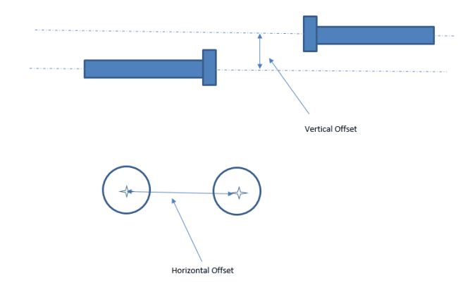
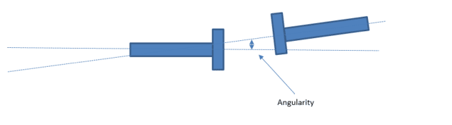
(iv) Angularity: It’s the angle between the two rotating shafts. It is generally measured in terms of slope.
(v) Soft Foot check: Soft foot is measured by loosening the mounting bolts and measuring the gap between the equipment and foundation. It can be measured using a feeler gauge or dial indicator. The soft foot should be rectified using a shim or machining the foundation
(vi) Reverse dial indicator method: Reverse dial indicator method is recommended by API for shaft alignment
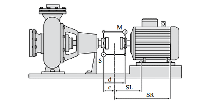
In the reverse dial indicator method, the dial indicator in the stationary and movable equipment is placed opposing one another on opposite coupling halves. The couplings are rotated 360 degrees and readings are taken at 0, 90, 180,270 degrees.
(vii) Laser Alignment: Laser alignment is used for critical rotating machines like Engines, turbines etc.
The advantage of Laser alignment over Dial indicators:
- Precise measurement.
- Results of misalignment can be obtained with just 90 degrees of rotation. Do not require to rotate 360 degrees
- Data storage and report generation
- Automated alignment correction results
(viii) During turning of the shaft ensure that bearings or gears are sufficiently lubricated.
4. PIPE INSTALLATION
Pipes are tubular sections that are used to convey liquids and gases to the desired location. Following points to be taken note of when installing a pipe to equipment:
(i) PIPE WELDING: As per class, oxy acetylene welding is not to be used for pipe welding for pipes whose wall thickness is greater than 10 mm
(ii) GTAW and GMAW are to be used for copper-nickel pipes welding
(iii) Butt-welded pipes are to be of full penetration type
(iv) Flanges of connecting pipe should not be sprung into position
(v) As per API 686, Pipe and equipment bolt holes should be within 1.5 mm offset. Bolts should be inserted into the bolt hole at ease, without external force
(vi) Upon connecting the flange, the flange gap should be measured using a feeler gauge. In the case of raised face flange, the reading should be taken at the raised face.
(vii) While the pipe flange is connected to the equipment flange, measure the shaft deflection using dial indicators to ensure pipes don’t impose stress on to the equipment
(viii) Eccentric reducers: Reducers placed in the suction line of a pump should be eccentric. This helps to prevent air pockets in the suction line. Note: The flat side of the eccentric reducers should be on top as shown in the below image
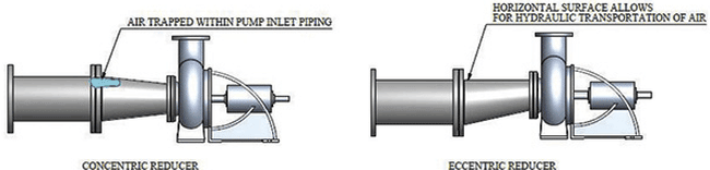
Why are reducers used?
Reducer help to connect the higher diameter inlet pipes to the pump suction. The inlet pipes are of higher sizes than the pump nozzle because a higher diameter helps to reduce frictional losses.
(ix) The pipe elbow in the suction line should be a long radius elbow
(x) Inlet piping should be of the same or larger than the inlet nozzle
(xi) Isolation valve: An isolation valve should be provided in the inlet and outlet side of the equipment. In certain cases, spectacle blinds are required in the inlet and outlet side to isolate the system
(xii) Strainers: Strainers should be located between the inlet isolation valve and equipment inlet connection. When a large accumulation of foreign particles is expected, duplex strainers shall be used.
(xiii) Pipe supports: Machinery inlet and outlet piping shall be supported as near as possible to the equipment. All the spring hanger turn buckle lock nuts should be checked for tightness. Piping spring hangers should be installed prior to the final shaft alignment. Verify there are no visible gaps between the pipe support and piping. In the case of an eccentric reducer in the pipe rack, the flat side has to face the bottom for maximum contact.
(xiv) Pipe hydro test: PH = 1.5 X P .
PH = test pressure
P – design pressure
For working temperatures above 300 degrees Celsius,
PH = 1.5 X (s 100 / s) x p
s100=permissible stress at 100 degree Celsius.
s = permissible stress at design temperature.
The hydro test may not be required on board if 100% radiographic examination indicates acceptable results.
5. COMMISSIONING: All pipe lines must be flushed and proved clean prior to commissioning. Strainers to be opened and check for foreign particles prior to commissioning. Perform a function test, prior to commissioning. As per class, all high-pressure pipeline flanges have anti splashing tape.
Over to you…
Do you know any other important points that can be added to this list?
Let’s know in the comments below.
Disclaimer: The authors’ views expressed in this article do not necessarily reflect the views of Marine Insight. Data and charts, if used, in the article have been sourced from available information and have not been authenticated by any statutory authority. The author and Marine Insight do not claim it to be accurate nor accept any responsibility for the same. The views constitute only the opinions and do not constitute any guidelines or recommendation on any course of action to be followed by the reader.
The article or images cannot be reproduced, copied, shared or used in any form without the permission of the author and Marine Insight.
Do you have info to share with us ? Suggest a correction


Latest Naval Arch Articles You Would Like:


Subscribe To Our Newsletters
By subscribing, you agree to our Privacy Policy and may receive occasional deal communications; you can unsubscribe anytime.