

Understanding Watertight Bulkheads In Ships: Construction and SOLAS Regulations
The safety of a ship in damaged condition is majorly dependent on the strength and integrity of its watertight bulkheads. There are a lot of factors that go into deciding the position of watertight bulkheads in a ship, and designing them structurally.
Watertight bulkheads are vertically designed watertight divisions/walls within the ship’s structure to avoid ingress of water in the compartment if the adjacent compartment is flooded due to damage in ship’s hull.
The position of the bulkheads along the length of the ship is primarily decided by the results of flood-able length calculations during the assessment of damaged stability of the ship. However, once their positions are fixed, there are a lot of factors coming into play, for example: types of watertight bulkheads, their uniqueness based on their position, structural design, etc.
Collision Bulkhead
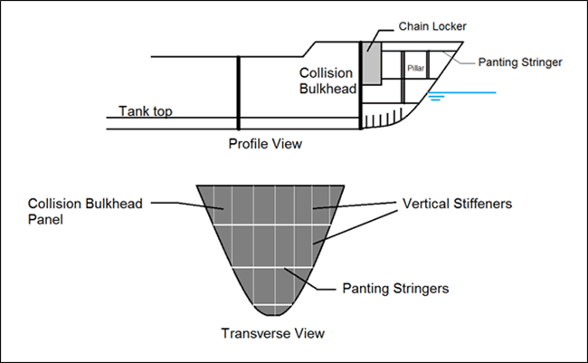
A collision bulkhead is the forward-most bulkhead in a ship. There are two factors that determine the position of a forward collision bulkhead. The final position of the collision bulkhead is so decided that it takes into consideration both the factors listed below:
Factor 1: Position based on flood-able length calculations.
Factor 2: Position based on the classification society code books. Most of the classification society rules have an allowable range of distance at which the collision bulkhead can be placed from the forward-most point of the ship’s hull. This distance is usually a function of the length of the ship and factors related to the shape of its bow.
Factor 3: Position based on SOLAS rule, which states that the collision bulkhead should be located aft of the forward perpendicular at a distance not less than 5 percent of the ship’s length of the ship or 10 meters (whichever is less). The distance must also not exceed 8 percent of the ship’s length.
However, the position of the collision bulkhead should be such that maximum cargo storage volume is achieved.
The collision bulkhead is a heavily strengthened structure, its main purpose being limiting the damage of a head-on collision to the part of the bow forward to it. To limit the damage to its forward region also means that the collision bulkhead is watertight bulkhead. It is usually vertically stiffened with sections of scantlings higher than those on the surrounding structures. It is also stiffened by triangular stringers of higher scantling, called panting stringers. Panting stringers are usually provided at every 2 meters from the bottom, forward of the collision bulkhead.
Related Reading: 12 Maritime Books All Seafarers Must Have
As per SOLAS rules,
- The collision bulkhead must be watertight upto the bulkhead deck. A bulkhead deck is basically the deck level upto which all the watertight bulkheads are extended.
- For providing access to chain locker room and the forward part of the bulkhead, steps may be provided on the collision bulkhead. However, this must not violate Factor 3.
- There must be no doors, manholes, access hatches, ventilation ducts or any openings on the collision bulkhead below the bulkhead deck. However, the bulkhead can be allowed to have only one piercing below the bulkhead deck for the passage of one pipe to cater to the fluid flow to the forepeak ballast tank. The passage of the pipe must be flanged and must be fitted with a screw-down valve which can be remotely operated from above the bulkhead deck. This valve is usually located forward of the collision bulkhead. However, the classification society certifying the ship may authorise a valve aft of the bulkhead provided it is easily serviceable at any condition, and is not located in the cargo area.
- In case of ships having superstructures at the forward region, the collision bulkhead is not terminated at the bulkhead deck. It must be extended to the deck level next to the weather deck. This would ensure sufficient structural continuity and keep the shear forces within safe limits.
- If the collision bulkhead is extended above the freeboard deck, the number of openings on the bulkhead should be restricted to a minimum in order to ensure sufficient buckling strength. All the openings should be watertight.
Related Reading:
Understanding curves of static stability
Construction of Watertight Bulkheads
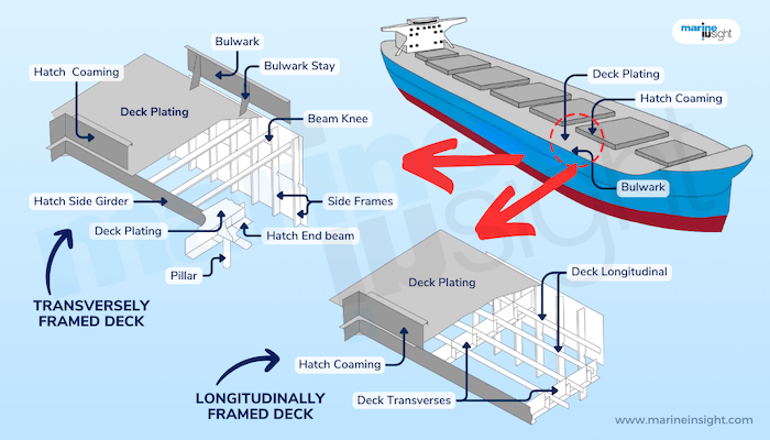
The primary function of watertight bulkheads is to divide a ship into a number of watertight compartments. Though most watertight bulkheads are transverse in orientation, some ships also have longitudinal watertight bulkheads within a compartment for longitudinal compartmentalisation within a compartment. Other than watertightness, the transverse bulkheads also add to the transverse strength of the ship. We will look into that aspect a little later.
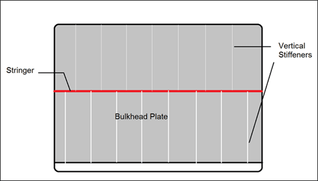
In small ships, a transverse bulkhead may be constructed from a single plate. However, for larger ships, the plating of a transverse bulkhead usually consists of a series of horizontal strakes welded together. But what’s interesting here is that, the thickness of these strakes increase with depth, in order to strengthen the bulkhead against the maximum hydrostatic pressure in case the compartment is fully flooded. So prior to erection, two dimensional strakes are first cut out from plates of different thicknesses.
The bulkhead plate itself is not resistant enough against large scale transverse forces like shear forces. So they are stiffened, either vertically or horizontally. But we usually go for the vertical stiffening instead of the horizontal. Why? Because horizontal stiffening in ships with high beam would require stiffeners of long span, which would also increase the scantling and weight of the stiffener, affecting usable cargo volume. However, with vertical stiffening, the span (and hence, the scantling) of the stiffener can be kept low by introducing a stringer at mid-depth (a stringer acts as a fixed end, therefore reducing the span).
The sections used for stiffening the bulkheads are usually flat bars, angles or bulb bars, depending upon the required section modulus. An important aspect of the design of bulkhead stiffeners is meeting the end conditions. In order to meet the boundary conditions so that the stiffeners respond as per the theoretical calculations, their end supports must be designed accordingly. At the upper end, they are attached to the underside of the deck plating with brackets, providing a hinged boundary condition. To achieve fixed ends, they are welded directly to the deck plate and the stringer.
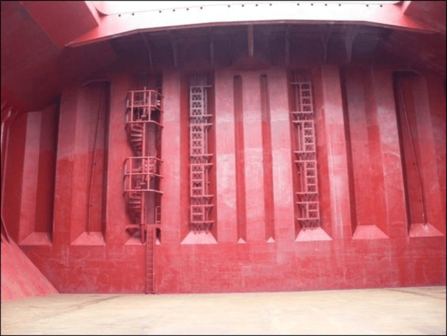
Most modern day ships use an advanced technology to achieve the required strength of bulkhead plates. They use corrugated bulkheads instead of stiffened ones. The corrugations are in the vertical direction, except when the breadth of the bulkhead is significantly low. However, there is one trade-off that needs to be made here. Since the corrugations are provided on the bulkhead plate right in the early fabrication stage, corrugated bulkheads are made of plates having uniform thickness (which is, the thickness equal to the lower most strake in case of a conventional bulkhead). This increases the weight of the bulkhead when compared to a conventionally stiffened bulkhead. In spite of this, usage of corrugated bulkheads come handy due to ease in fabrication and reduction of welded joints on the bulkhead.
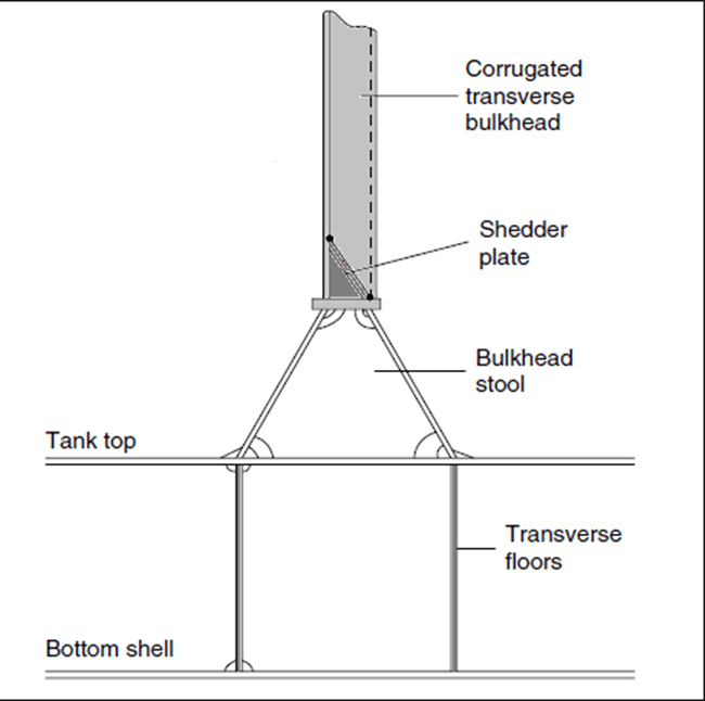
The above figure shows the elevation of a corrugated bulkhead from the side. In case of bulk carriers, in order to prevent accumulation of cargo at the base of the corrugations, the lower end of the bulkheads are provided with angular plates called shredder plates, which help in shredding the dry cargo to the tank top. The bulkhead is connected to the tank top by a bulkhead stool, which is fillet welded to the tank top plate. The two forward and aft ends of the stool is to be in line with the transverse plate floors. This ensures proper stress flow from the bulkhead to the plate floors.
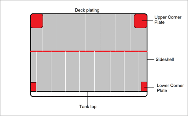
As shown above, the corners, where the bulkhead plate is welded to the side shell and the deck plate, or the tank top, separate corner plates are welded to complete the joint after welding the remaining bulkhead plate to the hull. These corner plates are provided for the following reasons:
- Fitting the entire bulkhead panel (with the corners) would be difficult from a production point of view since every structure is first fabricated with certain amount of green material. Before final installation, the green material is removed, and structures as huge as bulkheads require repeated checks for proper dimensional adherence. Eliminating the corners from this stage would reduce the complexity of maintaining dimensional precision at the corners.
- Stress concentration occurs at corners due to discontinuity of structure. In order to prevent this, corner plates are provided with additional thickness than the adjacent bulkhead plating.
Pressure Testing of Watertight Bulkheads
After installation of the bulkheads, they are to be tested for their integrity and water tightness. Since it is not feasible to fill all the cargo holds or compartments with water for this purpose, the test is done by a pressure hose. In this process, the bulkhead is subjected to a prerequisite water pressure from a hose for a fixed period of time, after which, the structural integrity of the bulkhead is inspected (checks are done for buckling and other deformations). Leak tests can also be done by pressurising the air in a compartment and checking for leakage of air to the other compartment.
Watertight Doors
Intactness is the primary purpose to be maintained by a watertight bulkhead. But in most ships, there are situations unavoidable where access from one compartment to another is a necessity. For example, an under-deck access from one cargo hold to another or from one compartment to another in case of passenger ships. In most ships, access to the shaft tunnel is necessary especially to monitor shaft oil temperatures or for repairs in the region. This purpose is solved by the use of watertight doors.
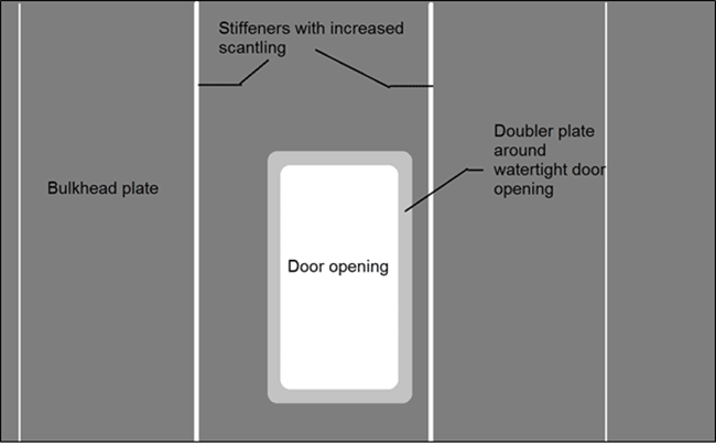
The bulkhead panel is usually cut out in a rectangular shape accommodating a watertight door. However, special incorporations are made in the structural design of the region around the door opening:
- The dimensions of the opening are kept to the minimum.
- An opening results in a major structural discontinuity, resulting in stress concentration around the opening. To maintain stress levels below safety limits, the opening is strengthened by doubler plates to increase the thickness of the bulkhead plate around the opening.
- If a vertical bulkhead stiffener comes in the way of the opening, it is terminated at the upper and lower edges of the opening. However, designers might choose to increase the stiffener spacing to avoid this. In that case, the scantling of the stiffeners adjacent to the opening are increased from the remaining stiffeners.
Watertight doors are usually hydraulically or electrically operated, and are either horizontally or vertically sliding. The reason why swinging doors are not provided in watertight bulkheads is because it would be impossible to close a swinging door in case of flooding. It must be easily operable even when the ship has listed to 15 degrees to either side, and the control system should be so designed that the door can be operated from the vicinity as well as remotely, i.e. from a position above the bulkhead deck. In all ships, visual indicators are provided at the remote control location to denote whether the door is open or closed.
Watertight doors are also subjected to pressure tests after installation to check for their structural integrity at design hydrostatic pressure in case of complete flooding up to the bulkhead deck.
SOLAS Rules Pertaining to Watertight Bulkheads
One of the most important regulations to be complied with during the design of watertight bulkheads and doors are that of SOLAS, and some important ones are discussed below:
- The number of openings for pipes and access should be kept to minimum in order to retain the strength of the bulkhead. In case such openings are provided, proper reinforcement must be provided so as to prevent stress concentration, and retain water tightness of the structure. Proper flanging must be incorporated in openings for pipelines and cables.
- Not more than one watertight door is allowed per watertight bulkhead. However, in case of ships having twin shafts, there may be two watertight doors, each providing access to the two shaft tunnels on either side. The mechanical gears required for manual operation of these doors must be located outside the machinery spaces.
- The time required to close or open any watertight door when triggered from the control room or navigation deck should not exceed 60 seconds when the ship is in upright condition.
- The transverse location of the watertight doors should be such that they must be easily operable even when the damage to the ship is within one fifth of the ship’s breadth from its side shell.
- Every watertight door should be equipped with an audible alarm distinct from all other alarms in the area. In case the door is being operated remotely, the alarm should start sounding at least 5 seconds before the door begins to slide either way, and must continue till it has completely opened or closed. However, if operated in situ, the alarm must sound only when the door is sliding. In case of passenger ships, the audible alarm must be accompanied by a visual alarm.
- All watertight doors that are accessible during voyage must be locked via an authorised unlocking system.
- Access doors and hatches on watertight bulkheads must remain closed when the ship is at sea. Visual indicators must be provided for every access hatch to indicate their status at the location and the navigation bridge.
Fire Class of Bulkheads
In order to prevent the propagation of fire from one compartment to another, all watertight bulkheads are also provided with fire-resistant paneling. However, depending on the extent to which bulkheads can retain the fire and smoke to the affected side, they are classified into three categories:
Class-A Panel: All watertight bulkheads are Class-A type. Bulkheads of Class A must be constructed of steel or equivalent material and should pass the standard fire test, preventing the passage of fire or smoke to the unaffected side for at least one hour. With Class A bulkheads in use, the average temperature on the unaffected side must not exceed 120 degree Celsius. Added to that, there are three categories of Class A panels depending on the time up to which the temperature at any point on the bulkhead must not rise above 160 degree Celsius:
A-60 Panel: 60 minutes.
A-30 Panel: 30 minutes.
A-15 Panel: 15 minutes.
A-0 panel: 0 minutes.
Class-B Panel: Bulkheads of Class B are constructed of materials that are approved by SOLAS and classification societies as incombustible materials. And should pass the standard fire test, preventing the passage of fire or smoke to the unaffected side for at least thirty minutes. With Class B bulkheads in use, the average temperature on the unaffected side must not exceed 120 degree Celsius. There are two types of Class B panels depending on the time up to which the temperature at any point on the bulkhead must not rise above 206 degree Celsius:
B-15 Panel: 15 minutes.
B-0 panel: 0 minutes.
Class-C Panel: Class C bulkheads and decks are constructed of materials that are approved by SOLAS and classification societies as incombustible, but they are not required to meet any requirements related to rise in temperature or passage of smoke and flame to the unaffected side.
Class A and B panels are used adjacent to most of the enclosed spaces within the ship, for example: cargo holds, control stations, stairways, lifeboat embarkation stations, galleys, machinery spaces, tanks, public spaces and accommodation areas. Class C panels are mostly used in open decks and promenades, where requirement of fire safety is minimum. They can also be used between two similar spaces if they are not separated by a watertight bulkhead, in which case a Class A panel is mandatory.
Disclaimer: The authors’ views expressed in this article do not necessarily reflect the views of Marine Insight. Data and charts, if used, in the article have been sourced from available information and have not been authenticated by any statutory authority. The author and Marine Insight do not claim it to be accurate nor accept any responsibility for the same. The views constitute only the opinions and do not constitute any guidelines or recommendation on any course of action to be followed by the reader.
The article or images cannot be reproduced, copied, shared or used in any form without the permission of the author and Marine Insight.
Do you have info to share with us ? Suggest a correction


Latest Naval Arch Articles You Would Like:

Subscribe To Our Newsletters
By subscribing, you agree to our Privacy Policy and may receive occasional deal communications; you can unsubscribe anytime.
Very informative article. thanks, Peter
Nice diagram with prompt informations
its thus illustrative
Very informative article, but I didnt find that info anywhere in the book I read. So can I get book references for corrugated bulkhead?
The class A and B bulkhead should have a temperature rise of 140 degree celsius and not 120 degree celsius and at a joint or place for class A bulkhead the maximum temperature rise is 180 degree celsius and for class B Bulkhead is 225 degree celsius.