

What Are “Structural Discontinuities” In Ship’s Structure?
Look around yourself, for any kind of structure; be it a beam of the room you are in, or the table you are using, or for that matter, your computer screen itself. Everything around us, is basically a structure. If you look carefully, you’ll note that there are regions in the structure that has an abrupt change in shape, or cross-section.
It may also be a sharp corner. Now imagine a ship, which is a combination of more than hundred structural components. There is not a single structural component in a ship that doesn’t feature the aspect mentioned above. This is what ship designers refer to as a structural discontinuity. A very obvious question that has popped in your mind now is why are we actually interested in discussing this? Is it ‘that’ important? Well, if you are related to ships in anyway, it is actually more important than you actually presume it to be.
Why deal with Structural Discontinuities?
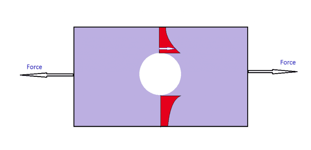
The best way to answer this question, is to delve into the structure itself. Let us, for example, consider a circular hole in a flat plate. Is it a discontinuity? Definitely! Keep referring to Figure 1 as you read further.
When the plate is pulled from both ends, it experiences stress. If the stress variation (in red) is plotted in way of the hole, it is observed that the stress in the vicinity of the hole is more than that in the edge of the plate. This is called stress concentration effect, and it takes place in regions near any structural discontinuity such as holes, notches, hatches, corners, etc. But why is this important?
Well, consider you are designing a structure for a safe stress level of σ MPa. And your structure has one or many such discontinuities. You will see, that your structure has started failing in those regions. Reason being, you designed your structure for the above stress level, but didn’t consider the effect of stress concentration, which has actually raised the stress levels to k.σ MPa (k>0; is called stress concentration factor) in regions of discontinuity. Your structure which you estimated to have a lifespan of five years, may start failing within four years. And for a ship, where the costs shoot above the sky, imagine making such a blunder!
Ship structures prone to discontinuities
Well, there are many types of discontinuities when it comes to ships. In order to get an organized overview, its better we discuss this in sub-points:
Ends of superstructure
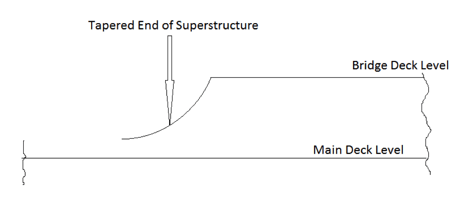
When talking about superstructure, let’s consider the poop deck, and forecastle and the accommodation superstructure. When seen from the profile view, these structures are sudden elevations in the profile of a ship. Well, a poop deck and forecastle, lying at the aft and for’d of a ship may not have adverse effects, but then consider the ends of a superstructure at the midship region. For example, a deckhouse or accommodation. The elevation looks pretty much as shown in Figure2. The effect of stress concentration here, is in addition to the maximum bending moment at the midship region, therefore making it highly prone to failure.
Ends of Longitudinal Girders
The girders that run longitudinally along the length of the ship, for example the centre girder, and the side girders, are to be terminated at the fore and aft perpendiculars. Since, by now you are well acquainted with the concept of discontinuity, you can clearly visualize that the sudden termination of these girders will lead to a discontinuity. How we overcome this problem will be discussed soon.
Deck Openings and other openings
A ship, in general, is always characterised by a deck opening. Every deck opening is basically a hole cut within a steel plate, be it in the form of a manhole, or a hatch opening. The only difference from the example in Figure 1, is that these may be of different shapes and sizes, depending on its functionality. But the physics of stress concentration works in the same way, raising the stress levels at the corners of the hatch openings. The same phenomenon occurs in openings like windows and scuttles. The design optimisations incorporated to combat these problems will also be discussed soon, once you get a hang of the various ways in which discontinuities can appear in a ship structure.
Special Case – Container Ships
A special case arises in case of container ships, which are equipped with torsion boxes. Due to a fine hull form, it gets difficult to taper the cross sectional areas of the torsion boxes in the aft and for’d regions, thus giving rise to severe structural discontinuity. However, in case you are thinking of omitting the use of torsion box, you are probably missing out the effect of torsion on container ships. Thus, such discontinuities are unavoidable, but can certainly be optimised.
Design methodologies to reduce structural discontinuities
It is by now evident, that discontinuities in ship structures are unavoidable, but they can certainly be reduced to considerable limits. So it’s time we discuss a few interesting ways the industry has adopted to reduce the effect of discontinuities:
Ends of Superstructure
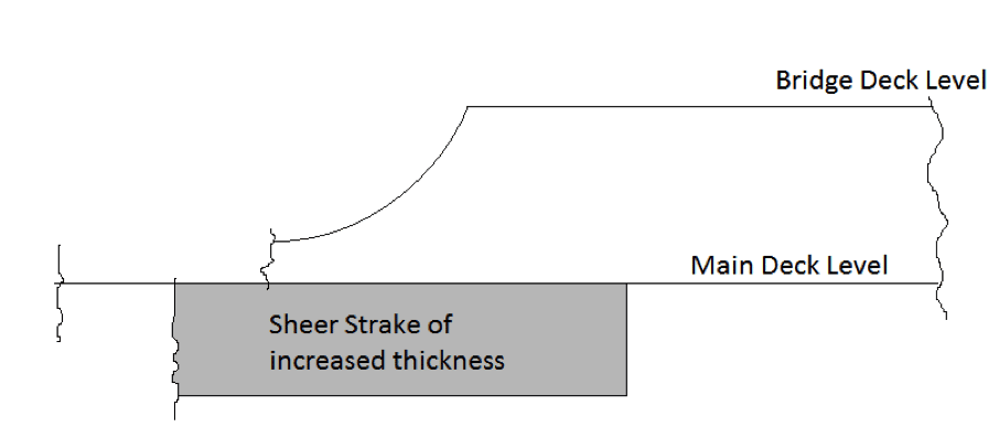
The ends of the superstructures are never abruptly brought down to the main deck level. Instead, to maintain structural continuity, the ends are tapered down to the bulwark wells, therefore reducing stress concentration in these regions. Well, did you ever notice that the sheer strake (the hull plating most adjacent to the deck) has more thickness than the remaining side shell? Wondered why is that so? If not, you’ve bumped into the right place. Superstructures that span throughout the beam of the ship are connected to the sheer strake. So the sheer strake partially shares the stress taken up by the superstructure ends, and since superstructure ends have a stress concentration, a thicker sheer strake can actually distribute the concentrated stress much effectively than a sheer strake having the same thickness of the side shell. Also, the thickness of sheer strake is increased by 50% in a superstructure region, compared to other regions of the ship. The effect is, an overall reduction in the stress concentration at the superstructure ends. Can you relate this to Figure 3?
Dealing with termination of longitudinal girders
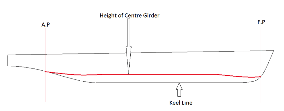
As described above, the termination of longitudinal girders at the forward and aft perpendiculars would give rise to structural discontinuity in the region of termination. How? Let’s take the centre girder for example. Looking at it from the profile view of the ship, it will have a certain height above the keel level. The question is, when we terminate the girder at the fore perpendicular or the aft perpendicular, how do we maintain its structural quantity. The solution is simple. The height of the centre girder is actually reduced very gradually as we move fore and aft from midship, a representation of which is shown in Figure 4.
Deck Openings and Windows
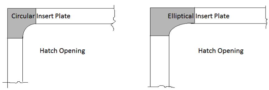
The problem of discontinuity related with deck openings, for example, hatch openings is that of sharp corners. Sharp corners are strictly avoided in structural design of a ship, due to this specific reason. Instead, the corners of hatch openings are maintained either circular or elliptical. In case of circular corners, the corner plate (also called insert plate, shaded in Figure5) is of increased thickness than the remaining plating surrounding the hatch opening. Whereas, recent designs use elliptical corners, which do not require increased thickness. This is basically because a circular opening has more stress concentration than an elliptical one, so to offset that effect, the circular insert plate is of increased thickness. Relate to this, in Figure5.
Importance of Regular Surveys and Inspections
Inspite of a good design, structural failure may be triggered by discontinuities if regular checks and surveys are not done on-board ships. Every ship is thus subjected to regular inspections, where the surveyors primarily focus on regions exhibiting prominent structural discontinuities. The reason behind such steps, is that even if a good design aims at reducing the stress concentrations, it does not totally eliminate the possibility of one. That is, a good structural design ensures the contract life-span only if regular checks are made to ensure that such stress prone regions are well within their limits of failure. In case surveyors find crack or crack propagations, essential replacements are made in order to prevent the failure from transforming into a global one, which in some cases have led to disasters at sea!
Do you have info to share with us ? Suggest a correction


Latest Naval Arch Articles You Would Like:

Subscribe To Our Newsletters
By subscribing, you agree to our Privacy Policy and may receive occasional deal communications; you can unsubscribe anytime.
thank you a lot
(edited)
Author,
I guess there is a mistake with stress concentration factor (K) value. K should be greater than 1. By writing K>0, it indicates K value can be from 0 to 1 which is wrong. K value never lies between 0 and 1.Correct me if I am wrong .
Regards,
Vignesh.
Hi Vignesh,
Yes, you are right. Thank you for pointing it out for us.