

Why Do Ship’s Hull Fail At Midship Region?
We have had a lot of marine accidents that involved failure of the hull structures. Whether it was a crack in the midship region, or a total split-off of the hull girder, or failures due to propagation of cracks, the crux of the matter boils down to a handful of causes that are of great concern to ship designers and operators. Mostly, crack propagation takes place due to fatigue, which is not something this article is about. This article gives an insight into the causes that lead to the failure of the hull girder from a longitudinal strength point of view. And before we start, we have to ask ourselves a few questions. Why have ships split-off? Why have many hull structures split-off after grounding? Why are midships highly prone to such failures? Is it because of a design flaw? Or for that matter, a glitch in the operation standards that have not been maintained?
Marine Engineers and ship operators use loading manuals to maintain the distribution of deadweight load on the hull girder. But what if the key to the design of those manuals lies in a deeper context? What if we tried to understand the phenomenon from a ship designer’s point of view? When ships are designed, a Naval Architect takes into consideration each and every factor that might affect the structural response of the hull girder with respect to the required loading conditions. In order to see the inner picture, we need to look at it from designer’s point of view.
When the hull girder of a ship is designed, the designers analyse the structure as a beam. But this beam is different from those that are used by civil engineers, in as much as ships are structures that are subjected to unpredictably variable loads. Look at it this way- the buoyancy on the hull is never predictable given the fact that sea surface being characterised by waves, the buoyancy on the ship is always varying periodically along the ship’s length. Also, ships are not always in the same cargo loading conditions. Where they may ply one voyage in a fully loaded condition, in the return voyage the ship may not have cargo but be induced to ballast loading condition. So we design the ship structure keeping in mind the uncertainty of the loads, and what helps in quantifying the response is a theory that has been widely used- Euler’s Beam Bending Theory.
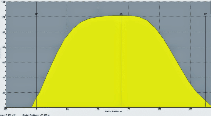
This great theory has been used by structural engineers in analysing the bending aspects of beams. Naval Architects have adopted this theory, but in a slightly different way. Unlike civil structures, a ship structure (which will be referred to as hull girder from now on) is always supported by an “elastic foundation” (sea surface). The direction of buoyancy on the girder is upwards, and its longitudinal distribution depends upon the longitudinal distribution of the ship’s underwater volume. Which means, there is more buoyancy at the midship region than the fore and aft ends. This leads us to a buoyancy distribution which looks similar to Figure 1.
There is another factor that contributes to the load on the girder. It is the weight that acts onto the hull girder; the weight comprising of individual weights of hull steel, machinery, outfit, cargo, fuel oil, lube oil, fresh water, ballast, and non-fuel cargo. Depending upon the longitudinal distribution of these weights and their individual magnitudes, we obtain the longitudinal distribution of load on the girder, which is referred to as Weight Curve. It is this load curve that holds utmost importance in the longitudinal strength aspect.
- Designers obtain the weight curve after developing the General Arrangement Plan of the ship.
- The load curve is subject to change, depending on the various loading conditions of the ship. For example, in fully loaded condition the load is generally more in the parallel mid body of the ship, i.e the region where most of the cargo is stowed, be it any type of a ship. But in ballast condition where aft and fore ballast tanks are to be filled up, the weight curve changes its shape owing to the increased weight at the aft and fore ends.
- Your loading manuals are basically a guide to load the ship by the design standards, which are nothing but inferences to these different conditions of weight distributions.
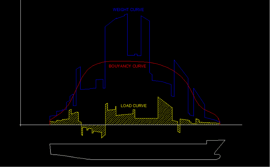
What we do next, is superimpose both the graphs and subtract the magnitudes of weight from the buoyancy at every point along the length to obtain the longitudinal distribution of total load on the girder, as shown in Figure 2. Notice how the direction of the net load may be upwards or downwards at different positions along the hull girder length, depending upon the buoyancy and weight distributions.
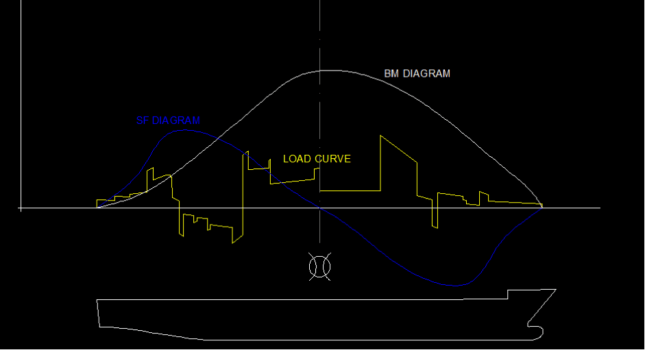
It is from this stage of the analysis that Euler’s Beam Bending Theory comes of great use. The theory says, if we plot the magnitude of area under the load curve from the aft end upto a certain point fore of the aft, we obtain the shear force acting on the hull section at that point. A longitudinal plot of this parameter gives us the distribution of the shear force, which is the SF Diagram of the ship at that loading condition. If such an area integration is performed on the SF curve, we obtain the Bending Moment curve of the ship for that loading condition, as shown in Figure 3.
This very diagram can answer all the questions that we asked in the beginning. The answers, along with some very important ship structural criteria as discussed below:
- The shear force on any transverse section of the hull girder is zero at the aft end, fore end and midships. So failure due to shearing is a least concern in these regions.
- The bending moment is always maximum at the midships. It is due to this effect, that the bending stress always reaches a maxima at the midship region of any ship, irrespective of its loading condition. The magnitudes may vary, but this nature is followed through any loading condition that the ship encounters in its lifetime.
- Owing to the maximum bending stresses occurring at the midships, designers consider the bending moment of midships as a threshold for design with a certain factor of safety.
- If in any case of loading, the bending stress at any section of the hull exceeds the bending strength of the material of the hull, it goes for a failure. So why midships? It is because of the maximum bending moment always occurring at midships, that the midship region is prone to exceed the threshold of bending strength of the material in a given condition of improper loading.
- Grounding has many a times resulted in midship cracks or split offs. Why? Try recalling what happens during grounding. Breaching occurs, resulting in unwanted load distributions along the hull, which result in hogging or sagging, which are nothing but modes of bending of the hull girder. So when you’ve seen ships split due to grounding, it is the bending moment at the midships that had already exceeded the strength of the hull material, and eventually led to the failure!
As mentioned earlier, the points mentioned in this article is not an exhaustive list of reasons leading to ship hull failure but enumerates causes that lead to the failure of the hull girder from a longitudinal strength point of view.
Over to you..
Let’s know if you have more points that should be added to this article.
If you have questions, please feel free to ask them at https://forums.marineinsight.com
Do you have info to share with us ? Suggest a correction


Latest Naval Arch Articles You Would Like:
Subscribe To Our Newsletters
By subscribing, you agree to our Privacy Policy and may receive occasional deal communications; you can unsubscribe anytime.
Hi.. nice and informative article. Keeping in mind the high variation of dynamic loads on the ship’s hull, what is the Factor of Safety you consider as a Ship’s designer? And how do you keep the SF zero at the two ends? From the plot, what I can understand is that the SF is a periodic function and varies along the length of the hull, this means, the loads are NOT point loads. So, do you assume UDLs or uniformly varying loads for generating the SF curve?
Himanshu, Thankyou. I’d like to answer your question in parts.
1) Factor of Safety: It depends. There is no such factor of safety for the entire ship structure. For example, the general design practice takes into consideration a FOS of 2 for material yield, and FOS of 3 for buckling failures. The question is, how are these determined from nowhere? Well, we calculate the Von-Mises stress on the structural members (applied axial stresses) and then compare it to the material strength. Depending on how low do we want the Von-Mises Stresses to be than the strength of the material, the FOS is decided. It also takes into consideration, the economic point of view. For example, you can always take a FOS of 5 for a case in which FOS of 2 was sufficiently safe. You’re still on the safe side, but your scantlings would increase, resulting in increase of lightship weight, and hence loss of deadweight.
2) The SF is not “kept” zero at both the ends. It is automatically zero, given the profile of the load curve of the ship. To make it simpler for you, the SF at a point is nothing but the area under the load curve from the left end to that point (considering area above the axis to be +ve and vice versa). As you approach the right end, the net area becomes zero, rendering zero SF at the ends.
3) You are right, that the SF is a periodically varying quantity (for a ship’s case), and so is the buoyancy curve, load curve and BM Curve. But you cannot understand that from this plot. Why? Imagine a ship is moving in waves (which are periodic in nature), and you take a random snapshot of the ship’s profile. Say this is Snapshot 1. The next second, you again take another snapshot- Shapshot 2. Now the plots shown here, are only for a random condition at any fixed time, for example, of Snapshot 1. If you calculate the same quantities for Snapshot 2, you are likely to get a slightly different plot (the values will change because the waves are periodic and have changed their profile by the next second, as a result of which the buoyancy curve has changed, even though your weight curve has remained the same. But since your buoyancy curve has changed, the load curve, SF and BM curves have also changed. In that case you would get slightly different values from that of Snapshot 1. However, the inherent natures of maxima and minima of the SF and BM would remain same, i.e SF would still be zero at the ends, and BM would still be maximum at the midships.
Hope that answered your question. Any further queries, feel free to ask.
I am seaman I need sum peper for marine`leavin in nigeria state delta state warri•homedress burutu n p a quaters burutu•all need help sir from angalabiri tony
Because in loading time deballast doesn’t fast
Why compressor lube oil turns black even though all parameters are normal, no white metal particles are found in the sump ?
lube oil is product of raw crude oil extracted below the surface of the earth which is black color….i work in aramco refinery and well heads
Commercial pressures at fast loading terminals with un mached vessel’s de ballasting capacity takes a toll over a period on the vessel hull & humans.
Im offshore motorman, and commissioning foreman, the issue is ballasting nt gd
When I was working onboard that particular ship as an electrician, I loaded my cable drumbs and materials in 1 far end of it. In the other end I put my toolbox down. That´s why the poor ship cracked and was about to sink in each end of it! End of story! If the painters had just remembered to paint it every day as they should have, it would still have been hanging in there! It was not my fault!
Or….
We was laying low South of Nigeria. As I was working, we got attacked by a bunch of pirate ships. They were clearly Agains labourers and a day of honnest work! They were all heavily armed with mashineguns and stuff! As they could hardly out manouver us, they savered us in half shooting at us midships, and trying to sink us. When it was not enough they realized the only way to stop us was, running their ship up our “sorry asses”. (No offence for the expression!) . That´s why!
I can come up with a million of explanations that sounds good…but by the end of the day? How do we really know for sure what happened if we did not see the accident as it happened? I wouldn´t have been minding not being onboard though….that´s for sure!
Wishing all a good day! Be safe!
Most of Taiwan high sea tankers always avoid PSC and other inspections due to their business don’t need to ship alongside at any port.Their operations are only high sea and anchorage to supply provision and store parts.PSC never ever come and checked at anchorage.So many seamen lifes are in still unreliable. Who can help us ?
I saw on a ship where they had place a 4″-6″ piece of rubber or synthetic material across the mid-ship so that the ship would not snap in two do to heavy wave action.
I think it was experimental, has it ever been used in production?
What are the effects of correcting heeling on a ship with a plank or structural damages concerning Bending Moment and Resistant moment?.
Is it constant the Moment of Inertia I of the vessel with respect the angle of heel?
Thinking in a heeling ship with a damage on the gun whale and the captain correct the heel taking ballast in the tanks. What happen with the Resistant Moment, in particular with the well- rounded Inertia Moment “I”. Bearing in mind that the trace of the Inertia Moment is a constant.
Oral exams question
Is hog better or sag ??
What will we answer ?
@Kunj: When the ship is loaded to its capacity, it is better to have Hog which will give the navigation officer some draft in hand to avoid overloading or exceeding the load line marks.
I am a retired Civil Engineer.I have read much regarding Ships Breaking their Backs over the years and as such find this subject very interesting.I have a Patent Pending World Patent on a new type of Clean Engine that is more than capable of replacing the 2/4 stroke Diesel Engine,it produces more Torque than standard 2/4 stroke Diesels, making it an ideal candidate to replace the massive 2 stroke Engines currently used in Ships such as the obsolete Knock Nevis Oil Tanker or large Container Ships that are used by Maersk. The Engine works on a system that would not only reduce fuel consumption drastically for these shippers, but would also remove the Broken Back issue on these huge Ships.As an added bonus the Green House Gas Emissions would be brought down by as much as 85%.
please kindly help me with self understanding note or lesson note on naval archtecture
Thank you for the enlightenment. Am new in the marine industry and want to know more of ship operations so I need more of such articles.
Glad you found it useful.